RT-1319B/URC PRC-113 VHF & UHF AM Radio
© Brooke Clarke 2009
This is a radio designed to allow
ground forces to communicate with aircraft on either the VHF AM
aircraft band (116.000 to 149.975 MHz) or the UHF AM aircraft band
(225.000 to 399.975 MHz) in 25 kHz steps. It's first use may
have been for the
GRC-206 Program
Pacer Speak used by Forward Air Controllers (FAC).
Also see my
MT-6250B web page for the
components of the GRC-206 system.
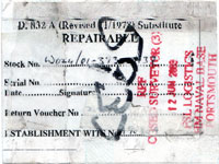
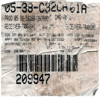
This particular radio came from the UK as "repairable". The
stick-on paper label shows the NSN to be 5820-01-393-5937 which
may be a special version of the RT-1319B that's different from the
U.S. version which has NSN 5820-01-286-8792. The difference
may be "Includes Telemetering Equipment".
Let me know if you have any details
on this particular version.
Contains a "Guard Receiver" tuned to the military
rescue/survival frequency of 243 MHz
but not to the civilian counterpart frequency of 121.5 MHz.
As of Feb 1 2009 the
SARSAT
system no longer monitors 121.5 and 243 MHz, the analog distress
frequencies and instead is monitoring frequencies in the 406 MHz
area that contain digital data. It's not clear what the need
is now in terms of "Guard Receivers"?
This manpack RT has been replaced (2009) by the newer hand held
radios that cover everything between 2 and 512 MHz.
This RT can be used with the
AM-7176
for for a VRC-83. A pair of VRC-83 radios for aircraft AM
communications (one for VHF and one for UHF) are used in the
GRC-206 (
PRC-104,
MT-6250)
Operation
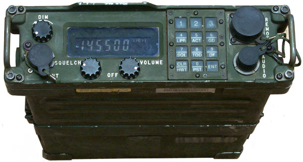
Press the digit keys for the
frequency, being sure to add any zeros to the end so that the
frequency display blinks. Then press ENT.
If you try to enter a frequency that's outside the range of the
radio the digit will not change or the whole frequency will not
blink.
Possible 2 meter AM ham frequencies are: 144.45 or 145.550 MHz.
Setting Preset
Turn VOLume control clockwise
Press ENTER
Enter desired frequency (display will be blinking)
Press 0/PST
Press appropriate channel number
Press ENTER
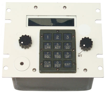
Keypad
1
|
2
|
3
|
4
LPR
|
5
ACT
|
6
GD
|
7
SQL
|
8
TOD
|
9
DF
|
CLR
HWT
|
0
PST
|
ENT
|
4/LPR
Low Power (2W) not 10 Watts normal
power. Press and hold button and LPR appears in
display just before PT (Plain Text)
5/ACT
ACTive Mode, i.e. Have Quick
Frequency hopping on the UHF band. (
Wiki)
6/GD
Press and hold to enable the guard
receiver (243 MHz). Press again to disable.
When guard receiver is active "GD" appears on the right bottom
row in front of SQL.
7/SQL
Pressing and holding SQL turns off
(or on) the Squelch so you don't need to change the squelch knob
setting.
8/TOD
When pressed and held the
frequency display left two characters change to:
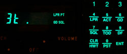
Note: LPR PT GD SQL are turned on in the display
Time Of Day is needed for frequency hopping and can be manually
set or set using a Have Quick time fill from a GPS receiver or
other source.
9/DF
Pressing and holding DF turns on
the transmitter and Direction Finding tone (1000 Hz) on the
current frequency. "DF" appears just to the right of the
rightmost frequency digit and centered top of bottom when it's
on.
CLR/HWT
CLeaR or Hard Wire Transfer
(remote)
0/PST
Pressing and holding PST begins
the process of working with PReseTs. The display changes
to P-n. Where n is the current preset. Pressing a
number key from 1 to 8 sets the value. Pressing ENT goes
to that frequency. The radio came with the
following. They must be stored in non volatile memory
since the radio came without main batteries installed.
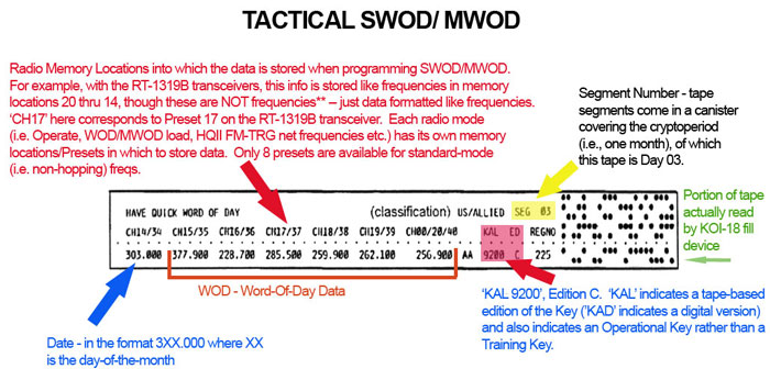
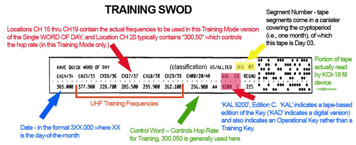
Word Of the Day (WOD)
The Word-Of-Day gets loaded
starting with channel (preset) 20 and working down to chan
14. It can be loaded manually by entering numbers that
look like frequencies then pressing 0/PST instead of ENT.
It can be entered using the
KOI-18
paper tape crypto fill device with a tape that has this
apparance (Thanks to C.W.):
Tactical Have Quick Tape Format
Training Have Quick Tape Format
ENT
Press ENTer to complete other
actions.
Press ENT to turn off the display (there is a battery saver
timer on the display that turns it off).
Display
The display is:
DDD.DDD
|
LPR PT
|
DF AM FM
|
GD SQL
|
DDD.DDD is the frequency in MHz
LPR when showing is 2 watts, 10 watts when not showing
PT when showing is Plain Text - when external
KY-57 is being used it does not show.
DF when Direction Finding tone is on.
AM - not sure since it does not normally show
FM - not sure (maybe this radio also does FM?)
GD - Guard receiver (243 MHz) is on when showing
SQL when the squelch knob setting is active, when off no squelch
is being used.
Versions
RT-1319
The original version did not
support Have Quick frequency hopping.
NSN: 5820-01-112-0050
This version is also known as (V)1.
RT-1319A
The second version supported the
first version of Have Quick in the UHF band.
RT-1319B
The latest version supports Have
Quick II in the UHF band that adds more to the message.
RT-6608 p/n: 914858-804 AN/GRC 206 (V) 3
NSN: 5820-01-286-8792
5820-01-393-5937
RT-1319B/URC
RECEIVER-TRANSMITTER SET, RADIO, Includes Telemetering
Equipment.
Receiver-Transmitter RT-1319B/URC (RT) is the same as
Receiver-Transmitter RT-1319/URC except for ECCM capabilities.
Changes in the data converter assembly, main receiver assembly,
and the guard receiver provide the ECCM features. In the
RT-1319B/URC, Part Number 914858-804, additional changes in the
data converter provide enhanced ECCM features not included in the
RT-1319B/URC, Part Number 914858-803. The ECCM features of these
RTs are covered in TO 31R2-2URC-62-1.
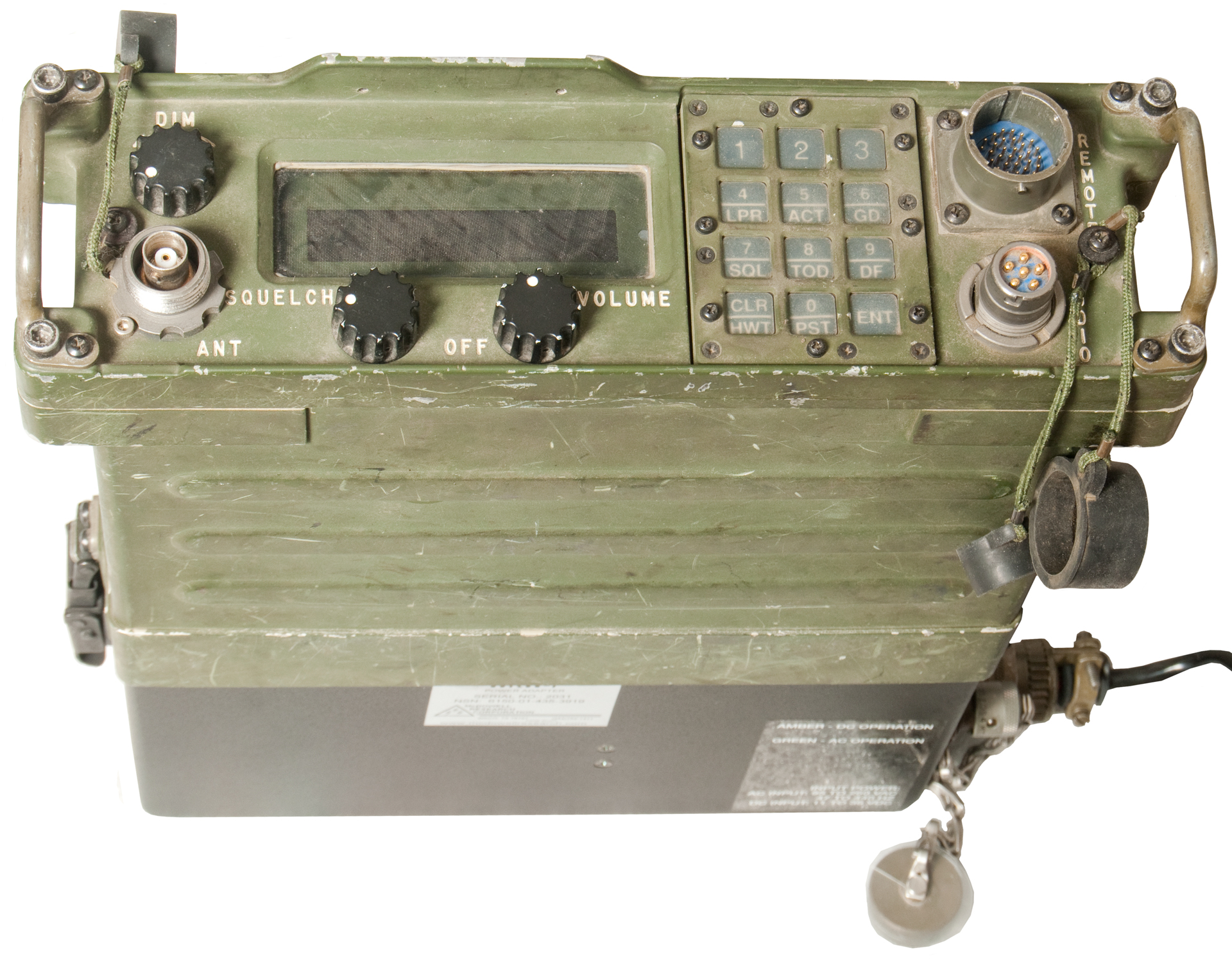
Configurations
PRC-113()
Manpack. Powered by two
BA-5590/U batteries. Uses stubby
dual band "donkey dick" antenna.
AN/PRC-113(V)1 is part number 706738-801
AN/PRC-113(V)2 is part number 706738-802
AN/PRC-113(V)3 is part number 706738-803 NSN: 5820-01-136-1519
VRC-83()
Vehicle system composed of
RT-1319(),
AM-7176 RF amp, MT-____
Mount
The VRC-83() is part of the
GRC-206
Program Pacer Speak FAC system.
Components of the GRC-206 on the
MT-6250
page.
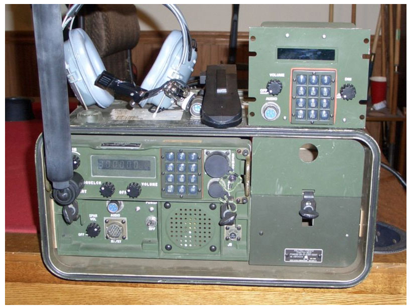
TRC-176()
This is a low power system that has the same RF output
as the RT-1319. The AM-7217 is an audio amplifier (no RF
function).
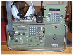 |
Notice that the antenna is
connected to the RT-1319 not the AM-7217 audio amp.
The space to the right it for an optional KY-57.
|
Inside the travel case are:
RT-1319
AM-7217 Audio Amp - AC mains or vehicle DC Power Supply
Storage compartments.
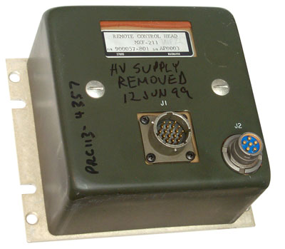
On top of the case are headphones, an H-250 handset and something similar
to the MX-211 remote called the
Remote Set Control C-11165.
|
The top and bottom covers
for the travel case have storage spaces for a number of
cables, the donkey dick antenna and other accessories.
The audio amp/power supply does not appear to have any RF
amplification capability and that's consistent with other
similar military units.
|
Jane's
says "The AN/TRC-176 is a member of the AN/GRC-206 family and
forms part of the Pacer Speak programme of the three US military
services. The TRC-176 consists of the RT-1319
transmitter/receiver, an equipment case, and a remote-control
unit. It is tailored for either desktop or rack-mounted
installations."
31R2-2TRC176-8-1 AN/TRC-176 OPER TEST PROCEDURES, AUTO TES
31R2-2TRC176-2 AN/TRC-176 MAINT INSTR WITH IPB (INTERMED
31R2-2TRC176-2 AN/TRC-176 MAINT INSTR WITH IPB (INTERMED
31R2-2TRC176-1 AN/TRC-176 OPERATORS MNL -- RADIO SET, TY
31R2-2TRC176-1 AN/TRC-176 OPERATORS MNL -- RADIO SET, TY
31R2-2TRC176-3 AN/TRC-176(V) MAINT INSTR WITH IPB (DEPOT) -
31R2-2TRC176-3 AN/TRC-176(V) MAINT INSTR WITH IPB (DEPOT) -
31R2-2TRC176-6WC-1 AN/TRC-176(V)1 SCHEDULED PERIODIC INSPECTION
31R2-2TRC176-6WC-1AN/TRC-176(V)1 SCHEDULED PERIODIC
INSPECTION
31R2-2TRC176-6WC-1-1 AN/TRC-176(V)2 SUPPLEMENTAL SCHEDULED
PERIODI
31R2-2TRC176-6WC-1-1 AN/TRC-176(V)2 SUPPLEMENTAL SCHEDULED
PERIODI
31R2-2TRC176-3-1 AN/TRC-176(V)2 SUPPLEMENTAL MAINT INSTR W/IPB
31R2-2TRC176-3-1 AN/TRC-176(V)2 SUPPLEMENTAL MAINT INSTR W/IPB
31R2-2TRC176-2-1 AN/TRC-176(V)2 SUPPLEMENTAL MAINT W/IPB -- IN
31R2-2TRC176-1-1 AN/TRC-176(V)2 SUPL OPR MNL -- RADIO SET, TYP
The
AN/TRC-176... - The PRC-113 is mounted on a Power
Supply/Audio Amplifier that accepts "12 Volts". The
separate remote looks like the MX-211 (See below) but it has the
U-183 connector on the lower left of the front panel instead of
on the rear panel.
DC Power
The PRC-113 is powered by two BB-590
or
BA-5590/U batteries connected in
parallel and delivering "24 Volts". The
5590BA Battery Adapter works.
It may be possible to power the radio using the REMOTE connector.
Panel connector has 3-lugs, 36 male pins, numbered in a
spiral. OD 0.972, ID 0.808 (5 standard key ways on ID).
Pins 2, 11, 12, 16, 22, 26, 27, 33 look like grounds and pin 17
has +30 Volts when the radio is powered from a pair of BB-2590
batteries.
Pin 16 appears to be an output rather than an input since it's a
higher voltage than the battery?
RT-1319/PRC-138 & WKW-7 Power
Supply as Battery Eliminator
|

|
ABP-AC/DC/BT-TR1
Transceiver Power Unit
Provides a universal input Uninterruptible Power Supply
when internal batteries are installed.
|
|
Metal Battery Box
NSN: 6160-01-251-6260
p/n 810599-801
|
Plastic Battery Box
NSN: 6160-01-468-0685
p/n: 10513-4800-02
|
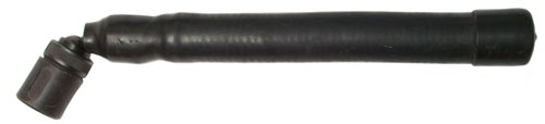
Antenna
The PRC-113 uses a single antenna
(donkey dick) that covers both the VHF and UHF aircraft
bands. It's a foot long and 1 1/4" is diameter.
There's a ball joint at the base with a threaded clamp ring to
allow positioning the antenna vertically when the RT is either
vertical or horizontal. NSN 5985-01-184-0035 Markings:
V/UHF 37695ASSY
8121059-1 63747 10047-1
37695 is the CAGE for RAYTHEON CO, 8121059-1
looks like a Magnavox p/n (they were acquired by Raytheon)
63747 is the CAGE for RADIALL INCORPORATED, 10047-1
is the Radiall p/n.
The VRC-83/GRC-206 uses the vehicle
mounted dual band dual connector
AS-3588/GRC-206
VHF-AM & UHF-AM Antenna
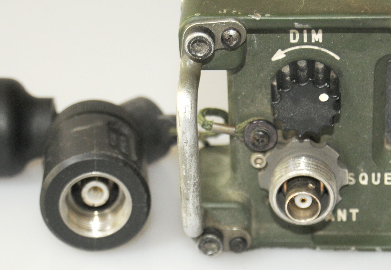
Connectors
A nice feature is that when any of
the dust caps are removed there is a place on the side of the
radio to anchor them unlike other radios where the cap dangles on
the end of it's tether.
Remote
Cable Connector has
sockets: MS 27467T15B35S (the front panel connector has
pins)
J2 Pin Out Table
Pin
|
Function
|
1
|
Plain/Cipher Ind-UHF/VHF
|
2
|
Shield Ground
|
3
|
Spare
|
4
|
Spare
|
5
|
Spare
|
6
|
PTT Indicate
|
7
|
Display Data
|
8
|
Display Clock 1
|
9
|
Receive Audio Fixed
|
10
|
Ext TOD In (from GPS)
|
11
|
Shield Ground
|
12
|
Power On/Off
On/Off Vol switch to (26,27,33,2,11)
|
13
|
Remote Select A
|
14
|
Remote Select B
|
15
|
Remote Select C
|
16
|
+24V Return (PS ground)
|
17
|
+24V Switched
|
18
|
Squelch Ind (RETRANS?)
|
19
|
DMA out
|
20
|
Data Available
|
21
|
Ext +5 V |
22
|
Main AGC
|
23
|
Display Clock 2
|
24
|
Bite Fault
|
25
|
Ext TOD Out
|
26
|
Ground
|
27
|
Ground
|
28
|
Guard (243 MHz) AGC
|
29
|
+24V Vehicle Power
|
30
|
Push To Talk (PTT)
|
31
|
Ext Clock In
|
32
|
Ext Clock Enable
|
33
|
Shield Ground
|
34
|
Data 1
|
35
|
Data 2
|
36
|
Data 4
|
37
|
Data 8
|
Audio
Standard U-183 (
U-229 type) and uses the
H-250 handset.
Antenna
The electrical connector is a
standard BNC-f panel jack. It's surrounded by a 3/4-16
threaded sleeve that mechanically supports the stubby antenna.
A standard BNC cable or BNC based antenna can be used.
Manuals
31R2-2PRC-113-1
31R2-2PRC-173-1-1
31R2-2URC-62
31R2-2URC-62-1
31R2-2URC-63 Maint. Inst w/Ill Parts Breakdown
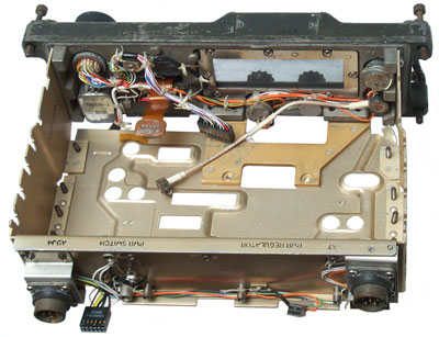
Maintenance
I did not see a JTAG (Wiki)
connector inside. The connection between the front panel
and main chassis is via a black 2xn type header, but it's not
JTAG.
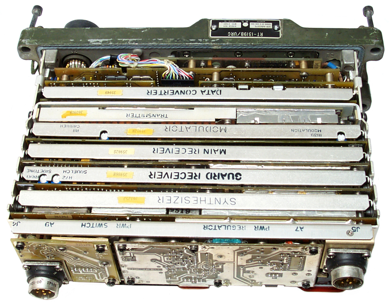
Assy
|
Assy #
|
Test Fix
|
T.F p/n
|
T.F. Man
|
Data Conv
|
A1A1A1 |
ATE
|
ATE
|
??
|
Tx
|
A1A1A2 |
TS-4093/URC
|
812542-801
|
TO
33D7-33-191-1
|
Mod
|
A1A1A3 |
TS-4092/URC
|
812544-801
|
TO
33DA48-25-1
|
Main Rx
|
A1A1A4 |
TS-4091/URC
|
812539-801
|
TO
33D7-36-51-1
|
Guard Rx
|
A1A1A5 |
TS-4091/URC |
812539-801 |
TO
33D7-36-51-1 |
Synth
|
A1A1A6 |
TS-4141/URC
|
815155-801
|
TO
33A1-5-497-1
|
Pwr Reg
|
A1A1A7 |
TS-4090/GRC-206
|
812540-801
|
TO
33DA7-17-1
|
Chassis
|
A1A1A8 |
na
|
na
|
na
|
Pwr Sw
|
A1A1A9 |
TS-4094/URC
|
812541-801
|
TO
33D7-33-190-1
|
What Goes Wrong
Related

PLGR to RT-1319 Have Quick Cable NSN
6150-01-375-8665
VHF air band radios
RT-53/TRC-7
MAW
UHF air band radios
MAY
PRC-14
PRC-41
URC-54
PRC-66
PRC-75
GRC-154
Links
Mike Murphy - has parts for the Am-7176
Audio-RF Amp
Target Corp - AN/PRC-113
(V) VHF/UHF Radio Set - specs look like OCR from hard copy
(i.e. have errors)
Back to Brooke's Products for Sale,
Military Information, PRC-68 Family of Squad Radios, U229 Audio Accessories, Audio Connectors, Electronics,
Home page
[an error occurred while processing this directive] page created 6 May
2009.


 05-33-C32CA01A