AM-7176A VHF/UHF AM RF Amplifier
&
MXF-220-1 Test Set
© Brooke Clarke 2014
Background
Description
Photos
Connectors
Cables
Controls &
Indicators
Problem
Manuals
Test Sets
Magnavox MXF-220-1 Power Supply and Watt Meter
Related
Links
Background
The RT-1319 is used to make
the PRC-113 manpack radio and it can also be used as part of the
PRC-240 mounted in an M998 or M1038 HMMWV
along with a KY-57, VRC-83 is just the
RT-1319 and this RF amp, GRC-206 is a four radio system that
includes two VRC-83 systems w/KY-57, one for VHF AM radio and the
other for UHF AM radio.
So far most of the manuals seem to be
titled VRC-83.
Description
This is a dual band RF power amplifier that works with
the RT-1319 to amplify either the VHF AM aircraft band or the UHF
AM aircraft band. It has a panel that looks like the battery
box for the PRC-113 radio with two battery sockets to provide DC
power to the radio. The radio front panel antenna connector
has a jumper that goes to the AM-7176 front panel so the AM-7176
has a T/R (transmit/receive) switch inside. There is also a
loud speaker in the AM-7176.
In Fig 3 below there is a green sticker that says:
"Warning, Remove batteries prior to shipment or active storage of
30 days or more" That implies that there is an internal keep
up battery.
Note: there are no BA-5590 type batteries in this system since the
AM-7176A supplies "battery power" to the RT-1319 by means of
connectors J4 & J5 that look like battery sockets.
Photos
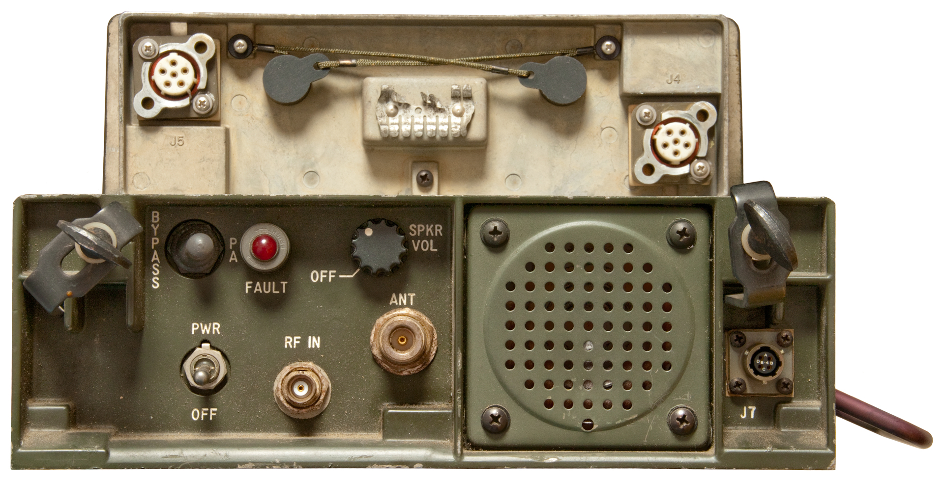
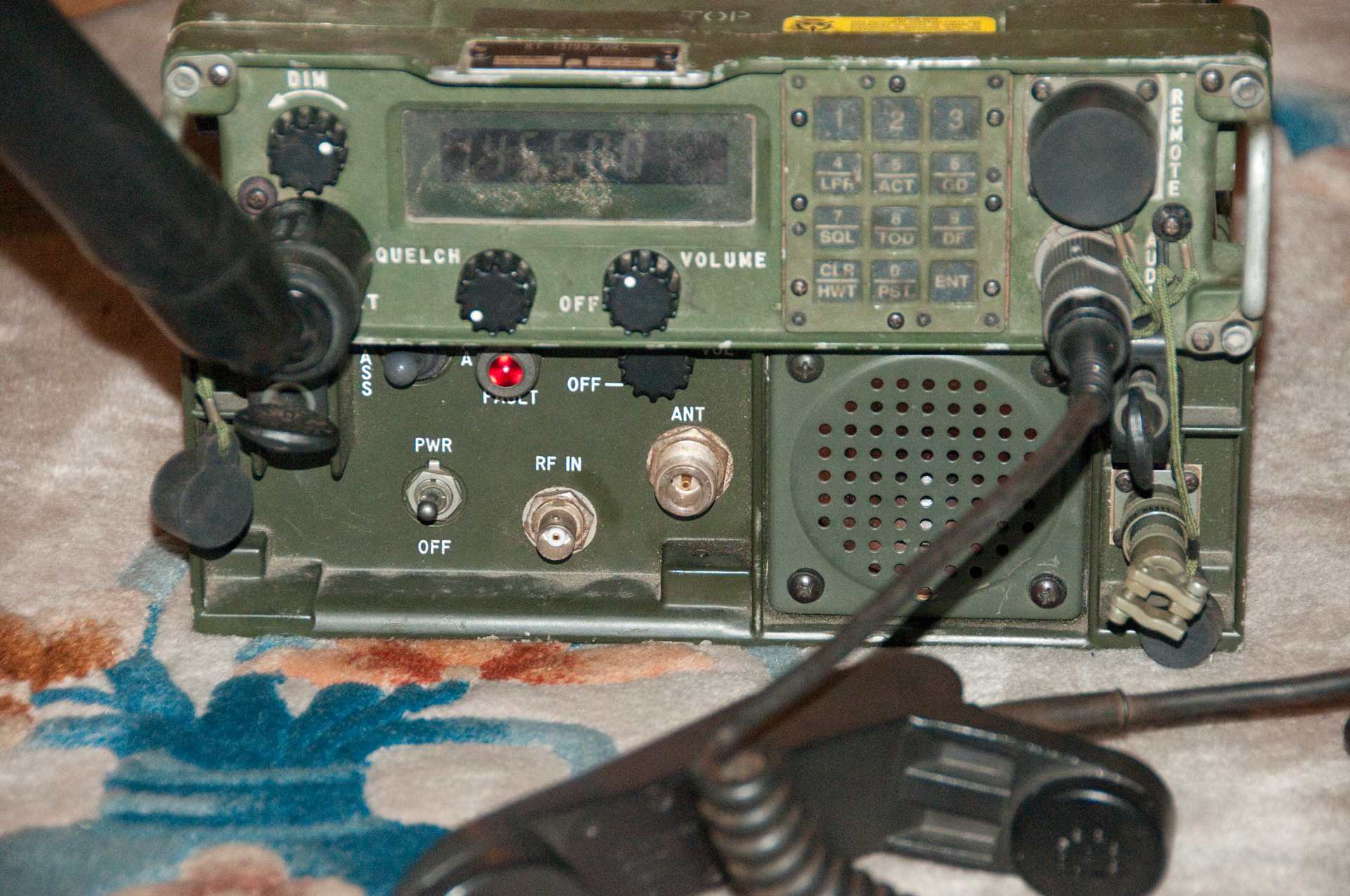
Fig 1 Front Panel
J5 & J4 Battery eliminator
RF In, Antenna & J7

|
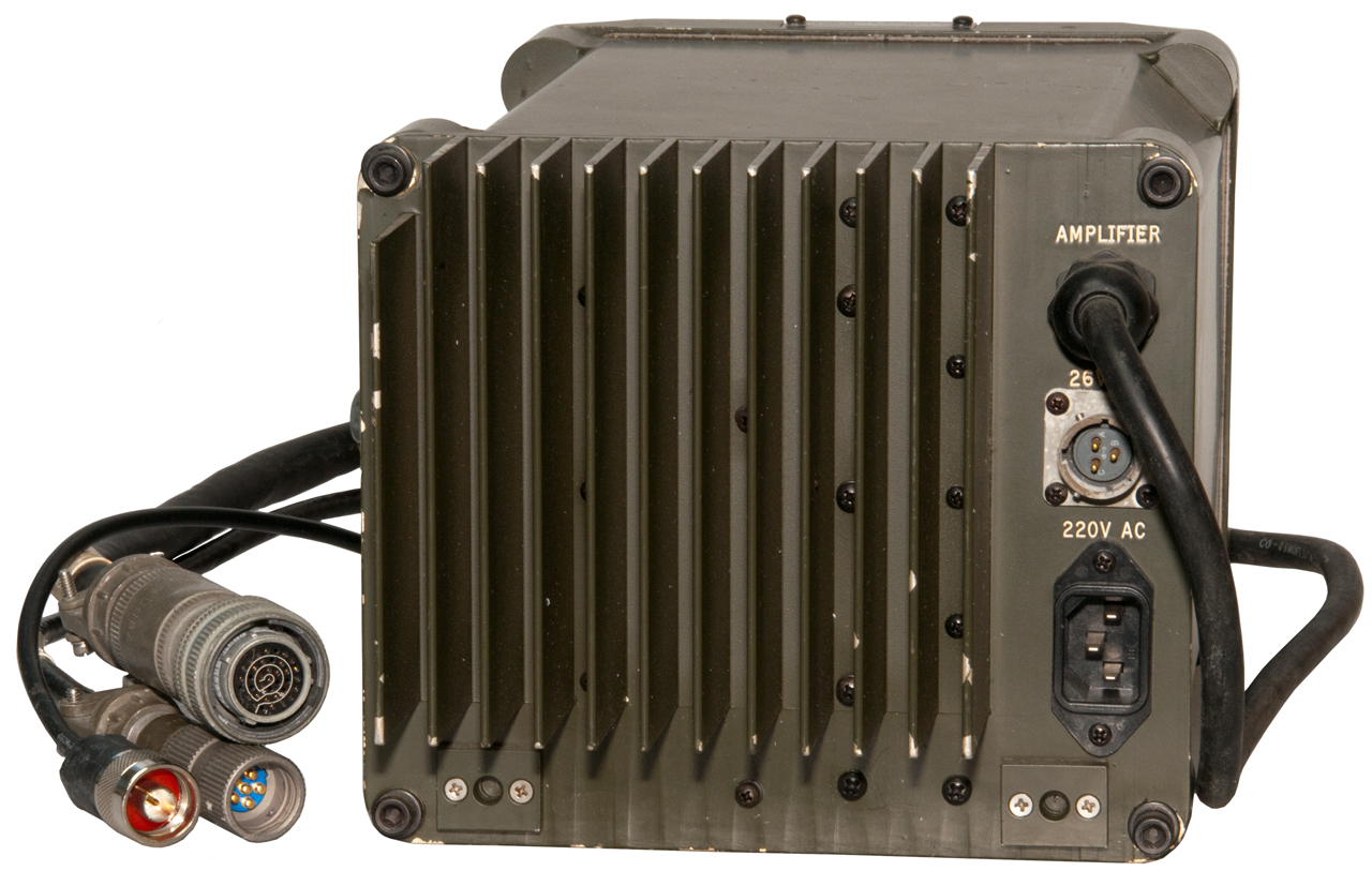
Fig 2 Rear J3 24 VDC Input

|
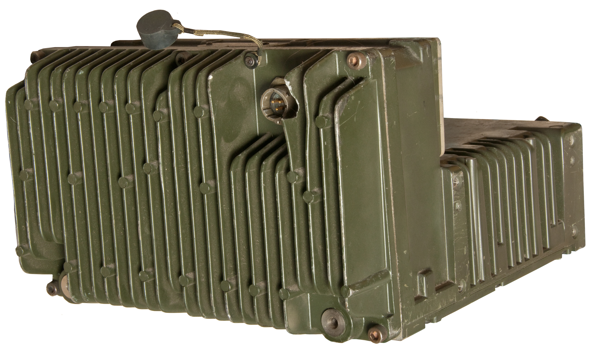
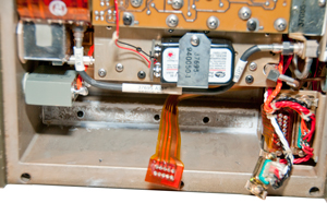
Fig 3 Side view, carry handle

|
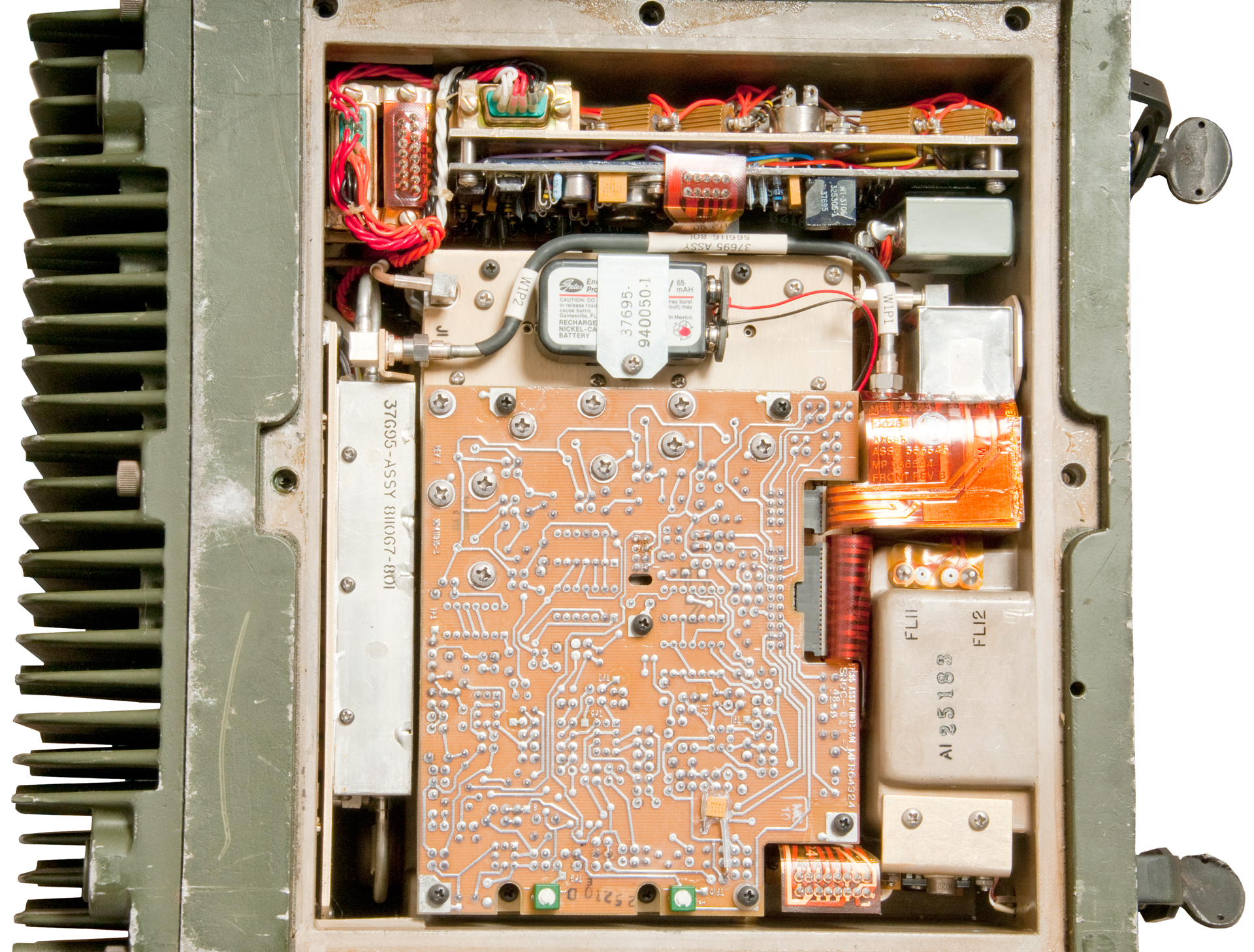
Fig 4 Bottom Cover
Removed
9V 65 mAh Ni-Cad battery
|
Fig 5 Front Panel J7 External Speaker and
5V keep alive
 |
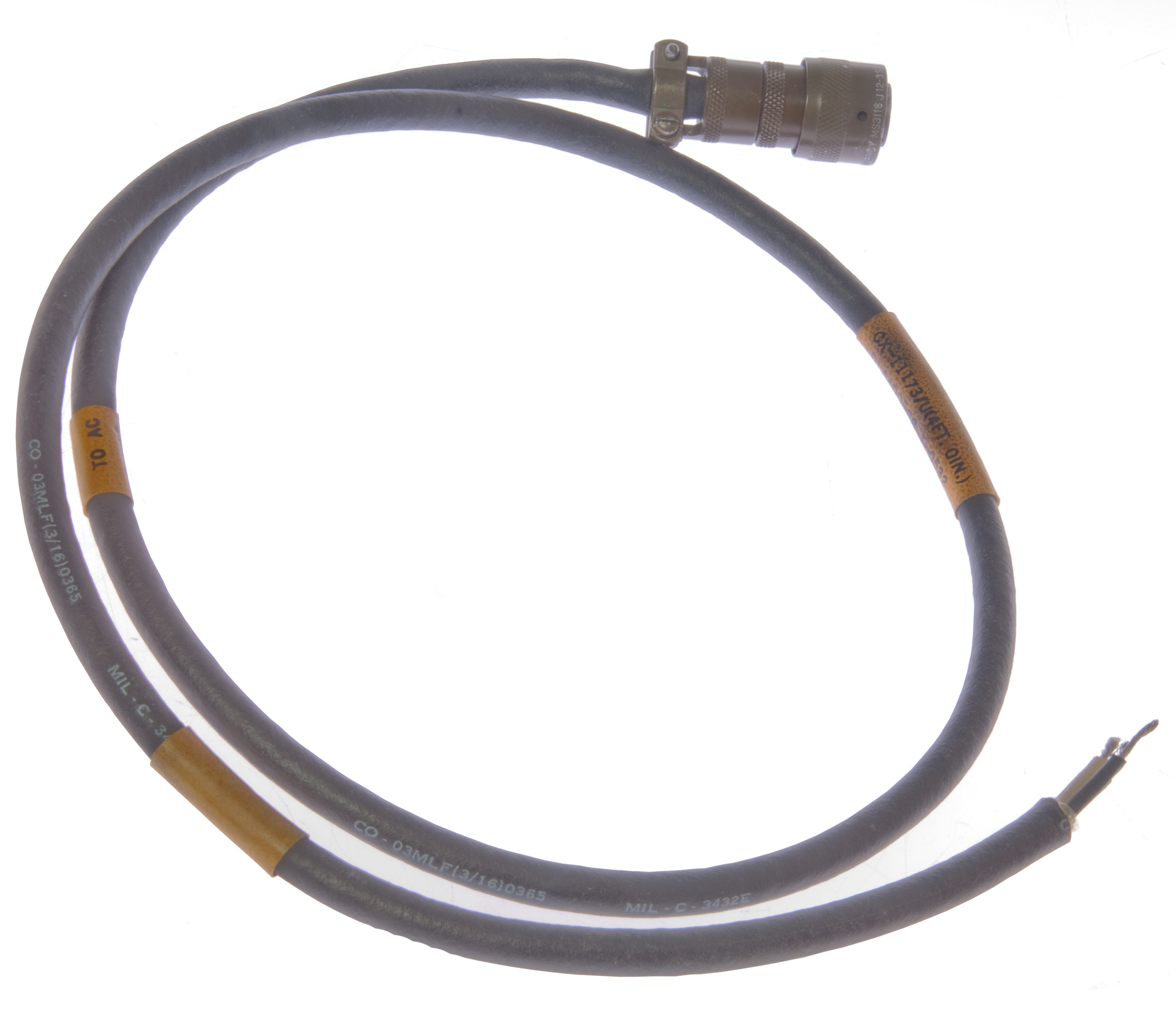
Fig 6 External Power Cable for J3 on back
CX-11173/U (4ft 0in)
MS3116-J12-3S
A: Chassis (white)
B: +24VDC (green)
C: 24VDC return (black)
 |
Fig 7 J3 Power Jack on rear
Top pins are A & C (Ground)
Bottom pin is B (+24 Input)

|
Fig 8 to remove finned assembly:
* loosen 6 each hex bolts w/ 3/16" driver,
* loosen 4 flat head screws holding DB connectors,
* use 5/16" ignition wrench to loosen SMA connector at J1
* Pull off other coax near J1
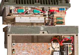
|
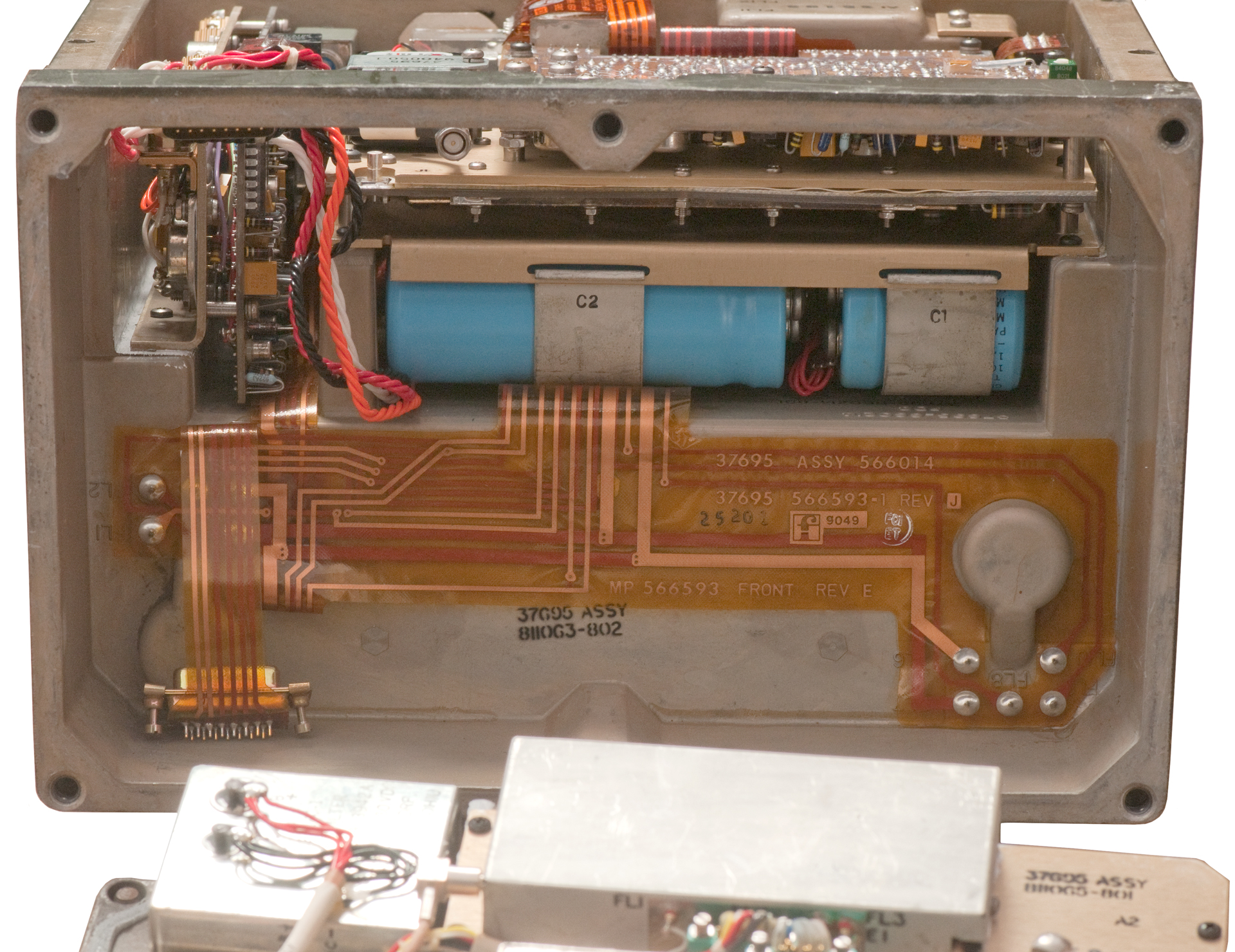
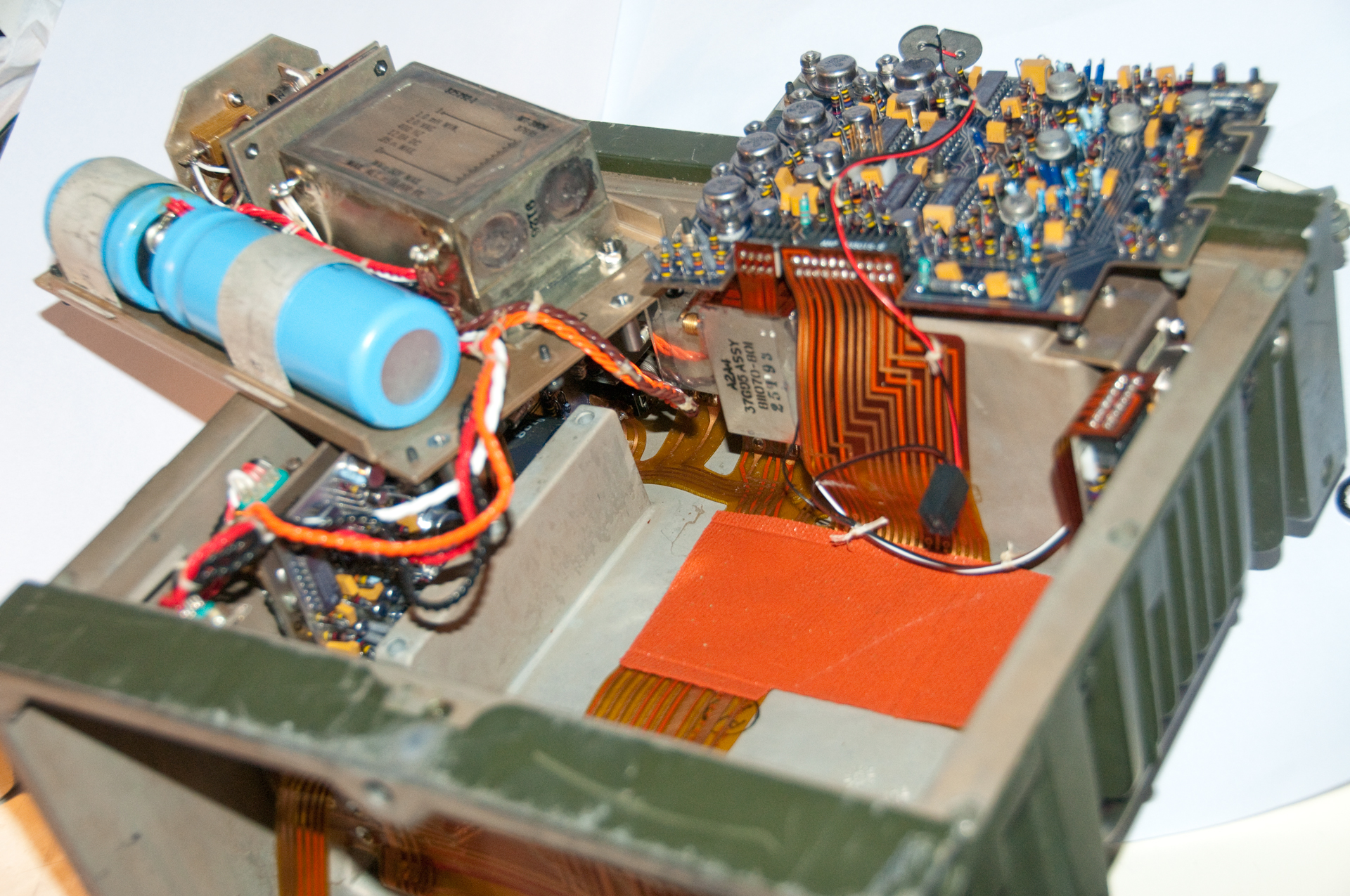
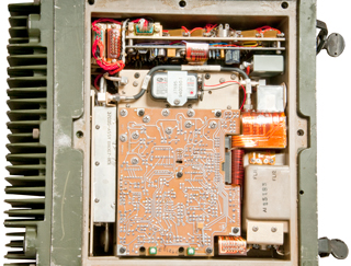
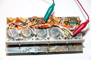
Fig 9 Inside A2A2 main chassis
A2A2A5-C1 is input filter cap
A2A2A5-C2 is output cap
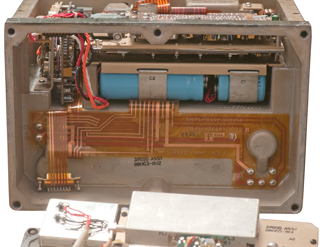
|
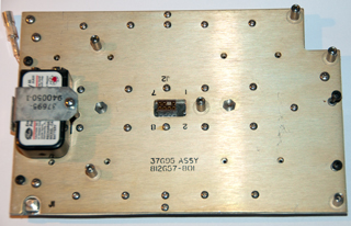
Fig 10 View of A2A1 finned assembly

|
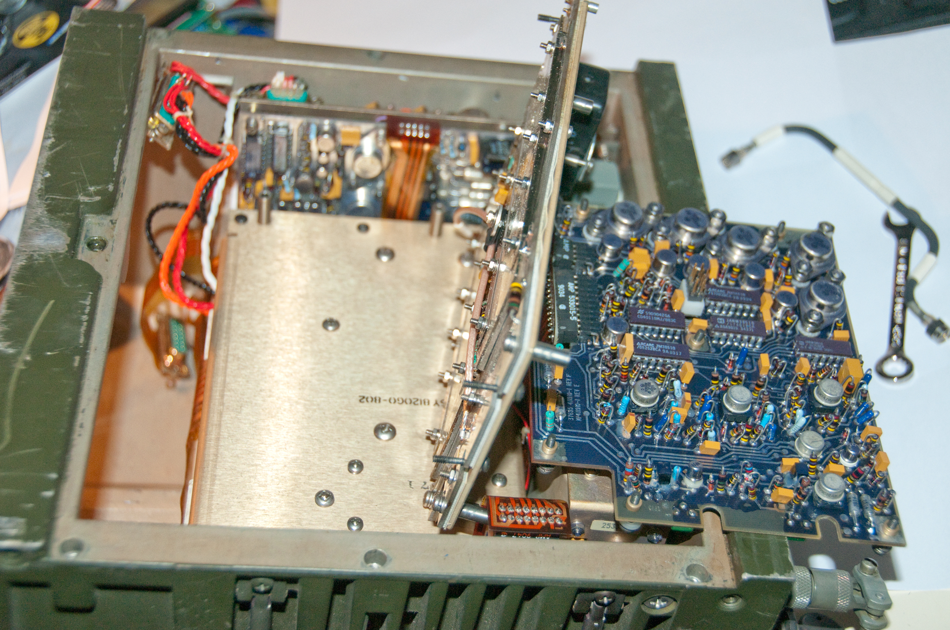
Fig 11 Chassis top PCB, loosen only black
screws
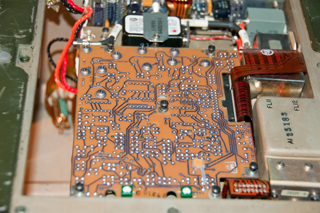 |
Fig 12 Loosen black screws on metal
plate, Pull coax under plate to disconnect and the
completely
remove plate (has 9V battery attached).

|
Fig 13 Loosen black
screws on top of the A2A2A5 input DC Filter assembly and
fold upside down.
|
Fig 14 A2A2A5 input DC Filter assembly now
accessible.
Note black connector on red & black wires. It
connects to the A1 board on the A2A2A5 input DC Filter
assembly

|
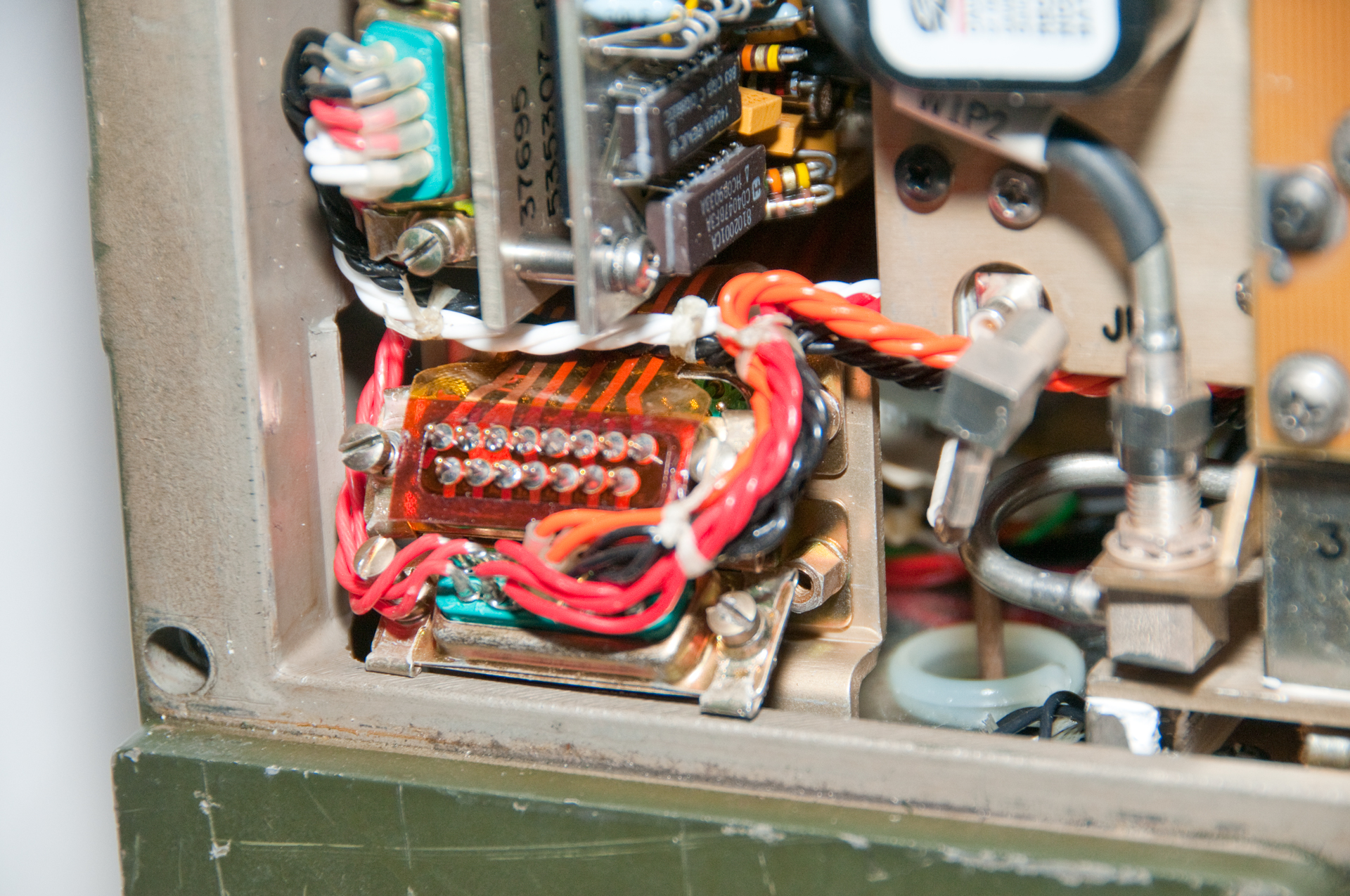
Fig 15 A2A2A5 input DC Filter assembly
The A1 board is standing up in the upper left. It
has a header
for the 9V battery input. Metal can is L1 (1mH
choke)
-802 has the A1 battery board.
C1 short Cap on left, C2 long Cap on right.
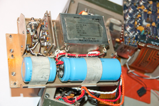
|
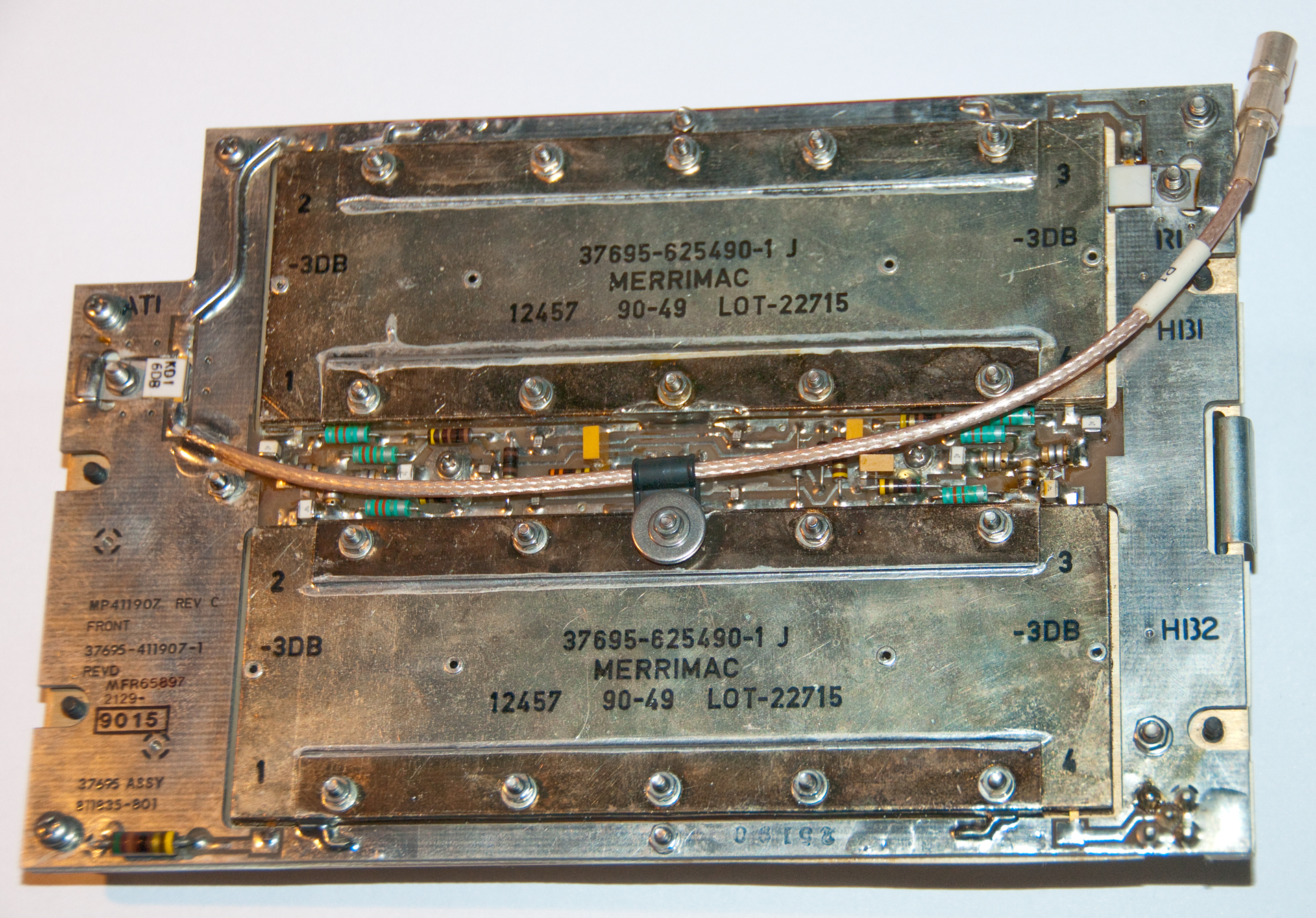
Fig 16 A2A1A3 Hybrid Coupler Assembly

|
Fig 17 A2A1A3 Hybrid Coupler Assembly
|
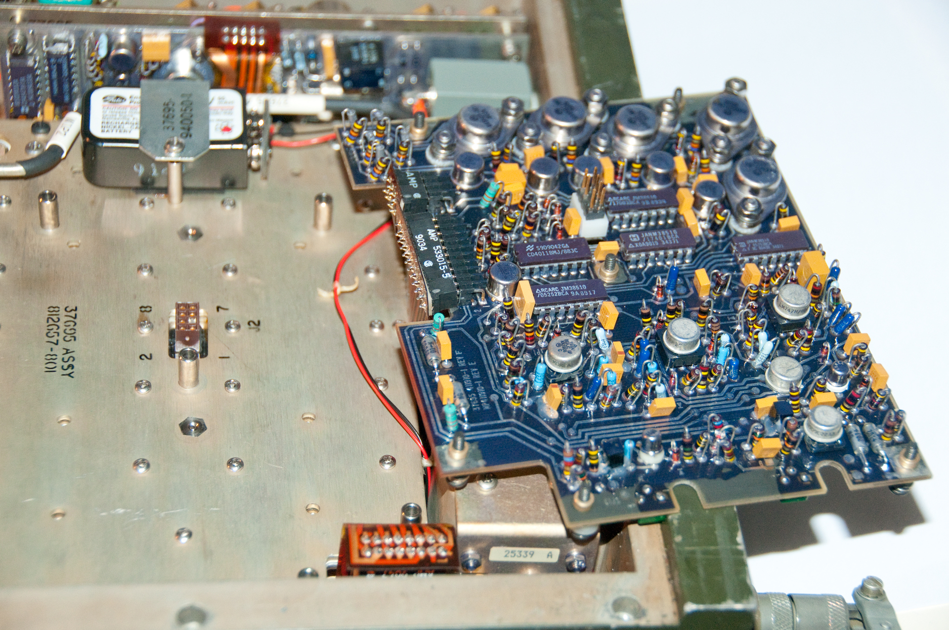
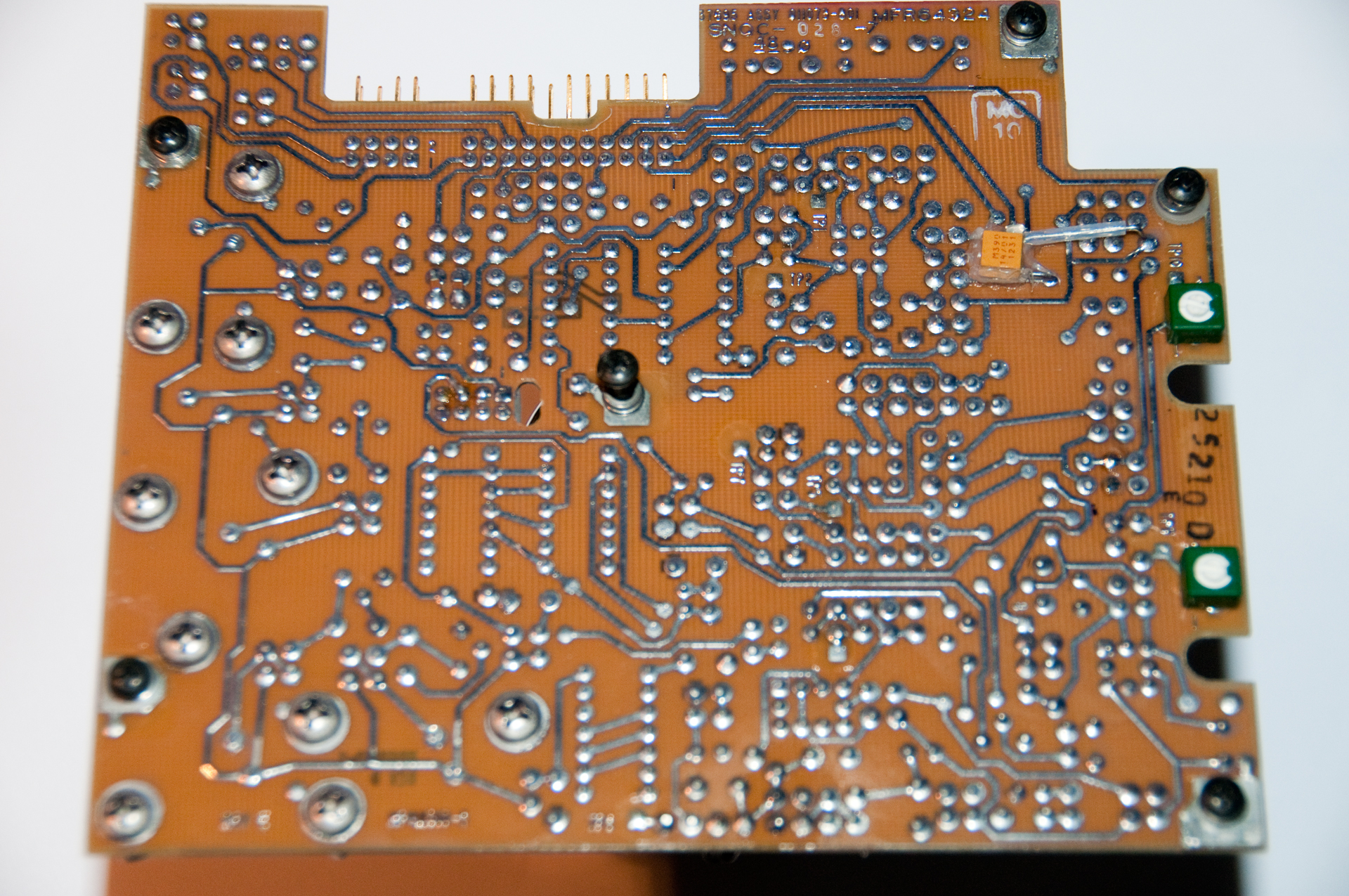
Fig 18 A2A2A2 Control Board

|
Fig 19 A2A2A2 Control Board
|
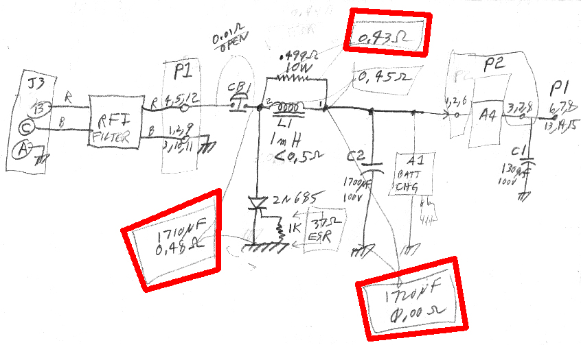
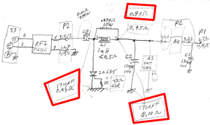
Fig 20 Troubleshooting DC Input Short
Hand Drawn DC Input Circuit & ESR-Cap meter readings.
|
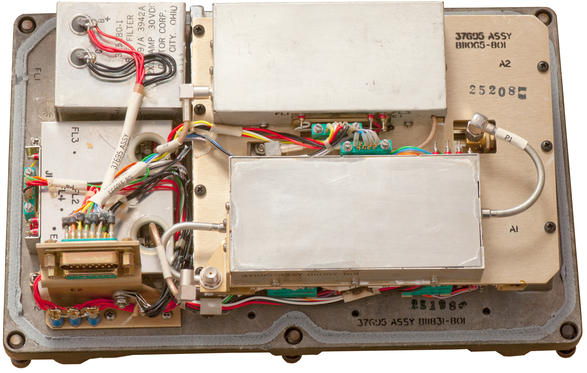
Fig 21 after mating the finned assembly
& chassis
4 connections: 2 each DB-9 and 2 each coax.

|
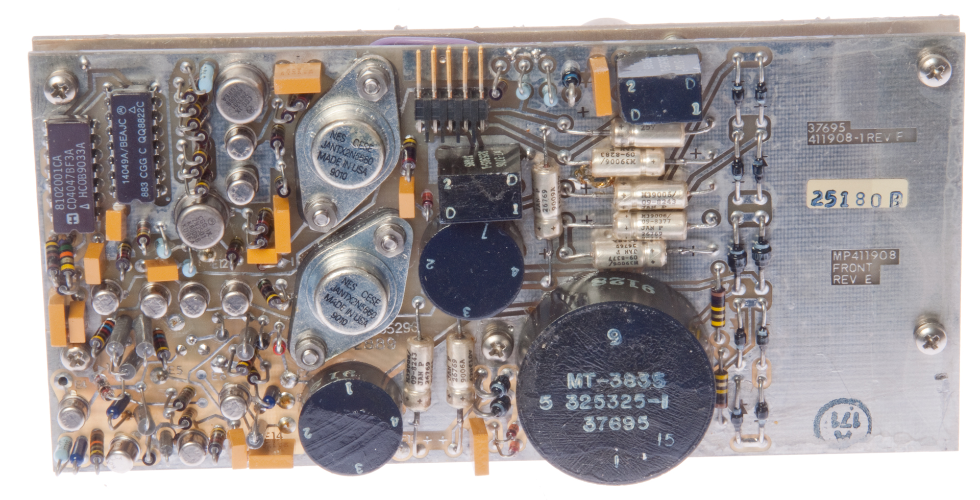
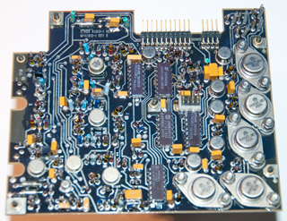
Fig 22 A4 Power Supply PCB side
A1J1 (2x5 header - missing pin #1) on PCB
Outputs:
+24 Reg Pin 2, 4
Gnd Pin 3,5
-100 V Pin 6
+5V Pins 7 & 8
+12V Pin 9
-12V Pin 10

|
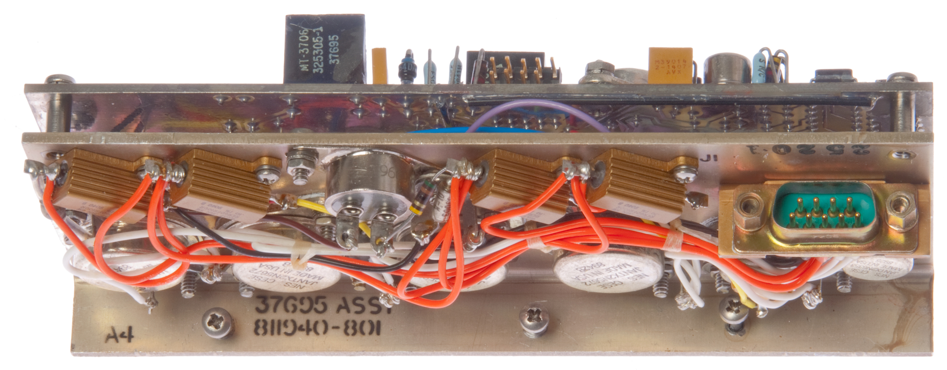
Fig 23 A4 Power Supply Heat Sink side
A2J1 (DB-9m) on heat sink
+24V In Pins 1, 2 6
Gnd Pins 4, 5 & 9
+24 Out Pins 3, 7 & 8

|
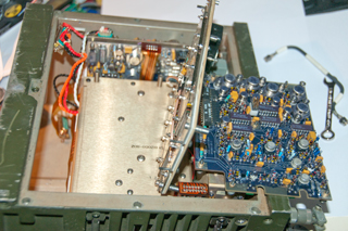
Fig 24 Chassis w/o A4 Power Supply
|
Fig 25 External +24 to A4 Power Supply
Black wires = Ground
White wires = +24 In
|
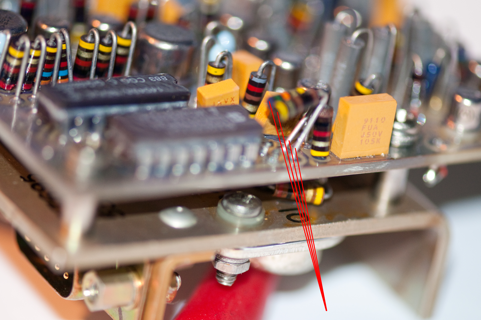
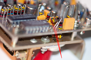
Fig 26 A4 Power Supply Broken Resistors
R21 (100R) & R22 (100k)just below U1 (555 timer) are
broken off. U1 was not powered, VR1 OK, tracing path found
these.
Also broken in Fig 22.
The actual R22 value is 75k, not 100k. The actual
R21 is 100 Ohms.
|
Fig 27 After repairing A4 PS
But missing the RF Coax.

Fault lamp most likely due to missing coax between RT
& Amp.
The cable is BNCm - BNCm, maybe:
NSN: 5995-00-823-2985
SM-D-415563-2Ft
Note: The Donkey Dick antenna will NOT fit on the
Type-N panel connector.
|
Connectors
AM-7176
|
RT-1319
|
J1
|
|
|
|
J2
|
|
|
|
J3
|
24 VDC In (Fig
6)
|
|
|
J4
|
Battery DC out
|
|
|
J5
|
Battery DC out |
|
|
J6
|
|
|
|
J7
|
5V Keep Alive
External Speaker
|
|
|
Cables
VRC-83 ID
|
Description
|
End
|
End
|
W1
|
DC Pwr |
AM-7176-J3 |
Vehicle Batt
Spade Term |
W2
|
RF
|
AM-7176-RF_In
|
RT-1319-Ant |
W3
|
Crypto
|
KY-57
|
RT-1319-Audio
|
W4
|
Memory
|
AM-7176-J7
|
RT-1319-Remote
|
Controls & Indicators
Bypass or Power Amp toggle switch
Fault warning lamp
Speaker Volume
Power On/Off
RF IN (from RT-1319 antenna connector)
ANT to VHF/UHF antenna
Front panel speaker
J7 external memory power supply.
Problem
Shorted DC Input
This unit came DOA (I knew that at the onset) with the
symptom of blowing a breaker. My hope is that it can be
repaired without detailed documentation.
After removing the finned assembly which contains the DC input
filter and RF power amp, the resistance between J3-B (+24VDC) and
either J3-A (chassis) or J3-C (-24VDC) shows as OL (Over Load) so
the problem is not in the finned assembly.
The next most likely place is the Input DC Filter assy (not the
EMI filter on the back of J3).
C1 and C2 can be measured with the ESR-Cap meter with the power
supply as is.
C1= 0.24 Ohms - 1530 uF [s.b. 01132U050AK - 1300uF 50V] so looks
OK
C2= 0.00 Ohms - 1720 uF (Fluke 87V DMM shows
falling resistance not short) ESR meter now reads 0.40 Ohms - 1720
uF [s.b. 101172U100AJ2A - 1720 uF 100V] so OK
So, the above two caps seem to be OK. They are in the DC
power supply Input Filter assy that contains CB1.
The power supply is connected to the chassis and to the two
printed circuit boards above it, so they will need to be removed
to get it out.
See Figs 11 to 19 above. Only back off the black captured
(+) screws.
With the Fluke 87 V DMM in diode mode (black to ground) it reads
1.1 V at C1+ and 1.0V at C2+ with power switch on or off.
Something is bad on the A2A2A5 input DC Filter assembly.
It looks like the 2N685 SCR or the 1k resistor from Gate to Anode
(ground). The resistance measures 37 Ohms.
Using the ESR-Cap meter on the SCR side of choke L1 shows 0.48
Ohms but on the C2 sice of L1 shows 0.00 Ohms ^ 1720 uF.
That's strange. So I opened one of the connections on C2 and
the circuit and C2 both look good. I think the problem was a
short between one of the black wires at the top of C2 and the
other terminal of C2. After reassembly the current draw is 0.042 A
not the 1+ amps it was.
-----
Note when reassembling First connect the molex connector on the 9V
battery wires to the A1 board on the A2A2A5 input DC Filter
assembly.
When the A1 assembly is complete and before installing the A1
finned assembly applying 24 VDC to C2 results in about 62 ma of
current.
Prior to placing the finned assembly into the chassis, position
the chassis with the bottom side down and the opening on the edge
of a table facing you. That way the flex cable and DB-9
connector will be held by gravity in the proper place. If
the chassis is in some other position the connector may be
trapped.
For a discussion of the troubleshooting method see the ESR-Cap
meter web page.
No Regulated 24 VDC on Battery Sockets
R21 (1oo Ohms) & R22 (75k Ohms) next to U1 have been broken
off. Replaced with single 100 Ohm and series combination
of 56K + 22K = 78K Ohms.
Now with 26 VDC input the A4 assembly (no output loads
connected) draws about 700 mA. The cases of the power
transistors show about 40 kHz.
The 2x5 post header has the following voltages:
-13
|
+6.5
|
-101
|
+26
|
+26
|
+13
|
+6.5
|
0
|
0
|
X
|
Manuals
TO 31R2-2VRC83-1-1 Supplemental Operator's Manual, Radio Set
AN/VRC-83(V)2, p/n 707123-803, 15 March 1985
TO 31R2-2VRC83-1 Operator's Manual, Radio Set AN/VRC-83(V)1,
p/n 707123-801, 15 March 1985
TO 31R2-2VRC83-2-1 TM w/Supplemental Maint. Inst, Ill Parts
Breakdown (IPB), Intermediate Level, Radio Set AN/VRC-83(V)2,
p/n 707123-803 & 707123-805, 16 July 2013
TO 31R2-2VRC83-2 TM Maint Inst w/ Ill Parts Breakdown (IPB),
Intermediate Level, Radio Set AN/VRC-83(V)1, p/n 707123-801, 31
Dec 2008
TO 31R2-2VRC83-3-1 TM Supplemental Maint Inst, w/ Ill Parts
Breakdown (IPB), Depot Level, Radio Set AN/VRC-83(V)2, p/n
707123-803, NSN 5820-01-127-3485 and p/n 707123-805, 30 March
2014
TO 31R2-2VRC83-3 TM Maint Inst w/IPB, Depot Level, Radio Set
AN/VRC-83(V)1, p/n 707123-801,NSN 5820-01-108-6622, 26 March
2014
TO 31R2-2VRC83-6WC-1-1 TM Supplemental Sched Peroidic Inst
Workcards, AN/VRC-83(V)2, p/n 707123-802 (ATOS), 1 Oct 2003
Incomplete without TO 31R2-2VRC83-6WC-1
Incorporates TO 31R2-2VRC83-6WC-1-1 dated 28 Feb 1995
TO 31R2-2VRC83-6WC-1 TM Sched Periodic Insp Workcards, Radio Set
AN/VRC-83(V)1, p/n 707123-801, 1 Oct 1984
Incorporates Supplement TO 31R2-2VRC83-6TP-1 dated 26
Feb 1995
TI-08946A-35/I Installation of UHF Radio Set, AN/VRC-83(V)2, in
Radio Sets, AN/MRC-138A & AN/MRC-138B, 4 Jun 1006
Test Sets (all test sets & manuals
WANTED contact me)
Nomenclature
|
Name
|
Magnavox p/n |
Manual
|
Description
|
| TS-4090/GRC-206(V) |
Power Converter Test Set |
812540-801 |
TO 33DA27-17-1
|
pots and switches, no meters
& 2 cables |
| TS-4091/GRC-206(V) |
Receiver Test Set |
812539-801 |
TO 33D27-36-51-1 |
speaker, switches, pot &
2 cables
|
TS-4093
|
Transmitter Module Test Set
|
812542-801
|
TO 33D7-33-191-1
|
3 meters & 3 cables |
| TS-4094/URC |
Multi-Module Test Set |
812541-801 |
TO 33D7-33-190-1
|
5 meters & 6 cables
|
OF-118/U
|
Test Adapter
|
|
TO 33D7-50-755-1
|
3 adapter boxes & 8
cables in suitcase
|
MXF-220-1
|
Adapter/Power Supply
|
901450-801
|
Wanted
|
see below
|
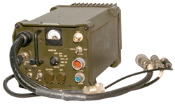
Magnavox MXF-220-1 Power Supply and Watt
Meter
This is an axillary piece of equipment to be used with
the AM-7176 typically in a base station.
Came from American
MilSpec.
My RT-1319 came from the UK and I expect that this unit is also
from the UK because in Fig 2 below you can see it's setup for 220
VAC.
Maybe there's a jumper change that will make it work on 115 VAC.
Controls, Indicators & Connectors
Y-cable (upper left) that connects to the RT-1319 REMOTE and AUDIO
connectors.
Amplifier RF Nm - goes to AM-7176 RF In
Pilot lamp with "press to test"
Power toggle switches for AC and DC
1/4" phone jacks for RECord and MICrophone
Monitor Switch: XMT AUD, REC AUD, REFL RF, FWD RF, AMPS, VOLTS
ANT Nm to ANT on AM-7176
Local Remote Control toggle switch
CONTROL connector -?
AUDIO (6-pin U-229 type)
Fig 1
|
Fig 2 note: 220 VAC sticker

|
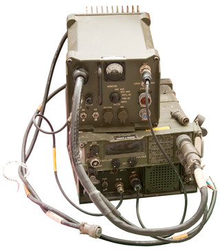
Fig 3 Photo 3 had wrong cable connections
Photo 4 should be correct.
|
Related
C-11166
Universal Remote System Control URSC
C-11169
Signal Distribution Unit SDU
SB-4151
Power Distribution Unit PDU
O-1814 Reference
Frequency Oscillator RFO
PRC-104 Manpack
HF radio
AM-7148 HF RF
Amp
RT-246 VHF FM
Radio
RT-1319 VHF AM
Aircraft Radio
RT-1444
Remote Control adapter for the RT-1209 (PRC-104)
KY-57 Transmission
Security Device for VHF and UHF radios
KY-65 Narrowband
Secure Voice Unit for HF radios
GRC-206 Cables
VRC-83 Vehicle version of PRC-113 with RF Amp Aircraft radio
covering VHF-AM and UHF-AM bands
There are three versions of the RT-1319, the first did not use
"Have Quick", the second used the first version of Have Quick and
the third used Have Quick II.
The RFO is in this system specifically to supply the RT-1319 with
TOD for Have Quick, so this system uses either of the Have Quick
versions of the radio.
AM-7176 - this page
HMMWV Hummer
1 ¼-Ton, 4X4
military
vehicle - M998 used for MRC-144
AT-1011 HF Whip
Antenna
AS-2259 HF NVIS
Antenna
AS-1729 VHF-FM
Ant
AS-3588/GRC-206
VHF-AM & UHF-AM Antenna
MT-1029 (lower
right mount for VHF-FM)
VRC-12 Series Radios
RT-246 VHF-FM
Radio
M455-1/GRC-206
Power Source (but pins are only 0.063" dia) How to make this power
supply work
let me
know. (maybe it has bad caps?)
EMCU 116 12 VDC
Input 24 VDC Output - The pins on this supply are the same size as
the GRC-206 input pins and so may be more suitable to power
it.
SINCGARS VHF
FM tactical radio,
RT-1439
KY-99 Advanced
Narrowband Digital Voice Terminal (ANDVT) Family (
FAS
web
site)
FM Bite/Audio
Interface -
Magnavox 812067-801 HF Antenna Mount - holds the
AT1011 HF antenna
MEP-025 DC
Generator NSN: 6115-00-017-8236 (aka: JHGV1.5A)
(not the 6115-00-889-1446 MEP-015 AC gen
set)
have: TM 5-6115-323-14, TM 5-6115-323-24P
28V @ <= 53.5 Amps (1.5 KW)
PP-1104 AC power supply
Input: 115 @ 24 Amps (
NOTE: Exceeds normal household
15A circuit capacity)
230 @ 12 Amps
60 Hz AC
Output: "12 Volt" 11.5 to 17.5 VDC (100 Amps @ 14
VDC)
"24 Volt" 23
to 35 VDC ( 50 Amps @ 28 VDC)
MT-6250 System Mount w/cables + info on
other components.+ overall photos
PP-6224
only 30 Amps at up to 30 Volts, maybe enough to run one radio and
the rest of the system.
J-4024/U GRC-206
Interconnecting Box - Allows connecting a DLED ((Dedicated
Loop Encryption Device) to either of 2 transmitters and either of
2 receivers and TTY machines.
Links
Back to Brooke's Products for Sale,
Military Information, U229 Audio Accessories, Audio Connectors, Electronics, Personal
Home, PRC68.com Contact, Alphanumeric
Index to web pages
Page created 23 Sep. 2014.