SSQ-53A DIFAR Sonobuoy
© Brooke Clarke 2021 - 2025 |
 |
Description
Displays
AQA-1 Indicator Group
AQA-5 Acoustic Signal Recorder
Audio Analysis
Patents
Side Scan Sonar
Photos
Patents
SSQ-53 Related
DIFAR
Magnavox
Autolycus - Sniffer
Related
References
Links
Background
Major Improvement in SONAR
During W.W.II the SONAR systems were both active, i.e. a ping reflected from a target would give bearing and distance or passive, i.e. an operator listened with headphones and might have a wheel to control the azimuth of the beam. But there were no spectrograms (Wiki) waterfall displays (Wiki) in W.W.II.
At some point the AQA-1 indicator group introduced the idea of the spectogram or waterfall display. Initially these were paper plots, but soon were made using CRTs connected to computers that did the Fast Fourier Transform (Wiki: FFT). The FFT converts the amplitude v. time signal from a hydrophone into a frequency spectrum display, which when stacked over time becomes the waterfall display.
While there's quit a bit of information on the W.W.II SONAR systems, there's very little about the modern spectrogram/waterfall systems.
Acknowledgements
This page was started as a direct result of seeing a YouTube video by FixitFrank titled: "SS-Q53A Hydrophone Sonobuoy Teardown Part 1". In addition Frank let me know the patent numbers 4029233 & 3921120 that appear on a metal plate that's part of the parachute-float assembly. These, and the patents on my Sonobuoy web page led to the patents below.
eBay seller wasurplusinc accepted my offer and so I'll have hardware to study.
Interests
Because of my interest in what I call Outdoor Intrusion Alarms, like the PSR-1 Seismic Intrusion Detector, I started the Sonobuoy web page because there seems to be a lot of similarity. I've done some reverse engineering on the SSQ-53B on the Sonobuoy web page. While reading patents related to the SSQ-53A I've learned that the hydrophone operates on the principle of a seismometer. The first sonobuoy, i.e. the CRT-1, uses an exotic Magnetostrictive device as the hydrophone. This had an omnicirectional pattern. So this pursuit has come full circle since this sonobuoy is using geophone technology in its hydrophone. Note the seismometer type sensors are excellent for sub sonic and infrasonic sound but not so good for higher frequencies, so an effort needs to be placed on the design of a seismometer type hydrophone so it can work at higher frequencies.
Description
The SSQ-53 family are what's called DIrectional Frequency Analysis & Recording (DIFAR) type acoustic sensors. This gives the sonobuoy operator magnetic heading information which is a huge improvement over the omnidirectional CRT-1. I've yet to understand how to receive and display the information.
I think there are a couple of ways to get the magnetic bearing (1) use some type of electronic compass such as a Fluxgate, or (2) have a permanent magnet in the sonobuoy so the body of the hydrophone is magnetically aligned with the Earth's field.
YouTube: Sub Brief: Whiteboard: Bearing Rate, 4:21 - Whiteboard: Jive Range (bearing rate), 13:27 -
Displays
The AQA-n series of displays (Sonobuoy Ref 28) were paper based chart recorders that displayed in raster format rather than use an ink pen. The display was a waterfall type where the paper movement provided the time axis and for the CRT-1 sonobuoy the other axis was frequency. For a DIFAR sonobuoy maybe the operator could select either or both a frequency or bearing waterfall?
A display of bearing versus frequency, known as a B-scan display, allows targets to be localized and discerned based on the estimated bearing presented to an operator. (Ref 2, pdf pg 38)
AQA-1 Indicator Group
This only processed distance and/or bearing angle information. No frequency or bearing waterfall displays. Probably post W.W.II (the P-2 Neptune became operational in 1947) and before the Korean war (Wiki: 25 June 1950 – 27 July 1953).
YouTube: PeriscopeFilm:
U.S. Navy Sonobuoy Indicator Group AN/AQA-1 Anti-Submarine Warfare Film 51114, 17:50, (no date) CONFIDENTIAL at that time.
@9:23: Handbook of Operation Instructions Indicator Group AN/AQA-1
@2:39: Function Switch (A receiver/B receiver)
Off@0:40 Was used on the Lockheed P-2 Neptune (Wiki - 1947 to 1984).
Standby
RO/RO: Range Only/Range Only - @3:31: A-Scope cursors, @5:41 propeller sounds, A-Scope cursor can be moved over ping return to get distance (with correct water temperature knob setting), 130 x 10 = 1300 Yards.
RO/DL: Range Only/Directional Listening - @ 3:33 A-Scope and triangular A-Scope - @12:36 SSQ-15 & SSQ-20
DL/DL: Directional Listening/Directional Listening - @9:06 - @11:04 propeller sounds but no freq v time plot
2 XR: Short Range Non-Directional Explosive echo ranging @14:14 SSQ-2B
10 XR: Long Range Non-Directional Explosive echo ranging
RCVR: bypass AQA-1 for headphone only listening
@0:56 SONAR operator (front) and RADAR operator (back)
@1:16 the AQA-1 and related R-316/ARR-26 Dual 16 Channel receiver & C-610/ARR-26 control box & PP468/ARR-26 Power Supply.
The C-610 is a vertical format control box with interphone functionality but the YouTube shows a smaller horizontal format control with no interphone function
@1:28 the SSQ-15 Echo-ranging sonobuoy (internal ping), the SSQ-2 (see 3022462) - Directional Listening (DIFAR) 32' depth, electric motor rotates hydrophone at 3 RPM with compass providing bearing information, 30 deg listening cone, or SSQ2B (Non-directional) requires external explosion.
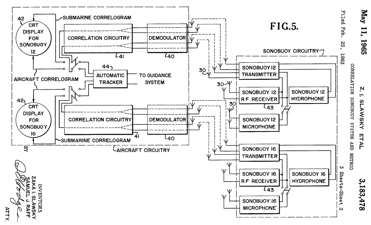
3183478 Correlation sonobuoy system and method, Zaka I Slawsky, Samuel J Raff, Navy, 1965-05-11, -
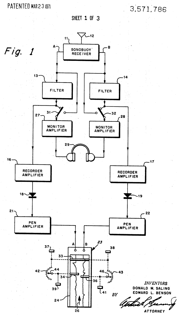
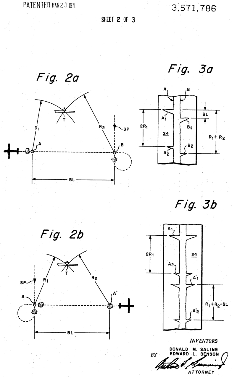
3571786 Graphic recording system, Donald Mureay Saling, Edward L Benson, Navy, App: 1961-11-29, SECRET, Pub: 1971-03-23, -
The ARR-26 is a Dual channel system, i.e. there are two independent receivers.
This has the look and feel of the AQA-1 except this version uses a pen plotter and the AQA-1 uses a CRT.
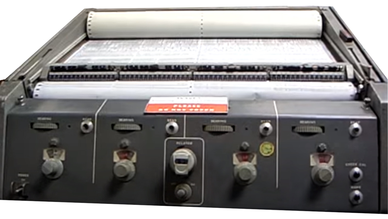
AQA-5 Acoustic Signal Recorder
It's not clear where or how the spectral analysis is done. The sonobuoy receivers typically have audio outputs so either the AQA-5 does the spectral analysis or there's another box that does it.
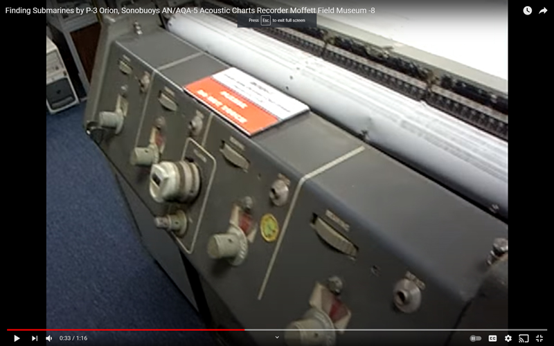
Image at left from YouTube:
Finding Submarines by P-3 Orion, Sonobuoys AN/AQA-5 Acoustic Charts Recorder Moffett Field Museum -8 used on the P-3A
Notice Roman numerals along bottom edge: I, II, III and to the right not seen IV. That's to say four sonobuoys can be displayed.
Note the take-up roll of paper at the top. New information is written at the bottom so this is a reverse waterfall display.
Assuming the sonobuoy is the CRT-1 then this is a frequency v. time waterfall. You would expect to see mostly straight lines of varying dot or dash lengths with only a small amount of "wiggle" in a line since that would mean a change in frequency.
Notice that the plot type for each channel is the same, but they change with time. There are 3 types:
At the front is Type1, behind that is Type 2 which is for less than half the time of Type 1, then at the back is Type 3 which is a little longer than Type 1. What are these? Let me know.
The front panel has a central multi-turn control and below that what may be a dual control knob/switch,
at the lower right corner there's a couple of push buttons most likely not part of channel IV.
at the lower left is probably the On/Off switch with wings to prevent accidental activation.
Each of the four channels has front panel controls:
Bearing (horizontal pot),
1/4" Head(phone) jack,
a control knob (switch) and associated illuminated (the small circular devices with 4 bumps are for 327 panel lamps) window to show ???
clip from the start of the YouTube video.
Photo sent from the Moffett Field Museum
I'm guessing the AQA-5 does the spectral analysis since it could then easily drive the plotting element (maybe a back and forth scanning stylus or a large number of fixed styli).
Manual of Navy Enlisted Classifications 1963 - AX-6523 Aviation ASW (Jezebel) Technician: a. S2D/E, AN/AQA-4 (V), Indicator Group System Maintenance (C-102-135), or b. P-3 AN/AQA-5 System Maintenance (C-102-163), or c. AN/AQA-3, AN/AQA-3A and AN/AQA-4V JEZEBEL Recorder Maintenance (D-102-019). Note: Qualified to maintain AN/AQA-3, 4 and/or 5 Jezebel equipment.
The War Zone: Confessions Of A Submarine Hunting S-3 Viking Crewman During The Twilight Of The Cold War - "He made an additional, critical point: “Add to all of this, the smell of burning carbon-based paper that will permeate your station as you search, for hours and hours...” The P-3C Update III, with plasma screens that replaced paper grams, had just achieved IOC—Initial Operating Capability—the previous year." - also has a blurry photo of a dual screen sonobuoy display.
Patents
2368953 Electric control system, Walsh Philip John, App: 1940-08-26, Pub: 1945-02-06, - includes relays operated by narrow band audio filters cited by 41 patents.
2376730 Apparatus for sonic detection, John R Steinhoff, Bell Labs, App: 1942-04-17, Pub: 1945-05-22, - uses audio band pass filters
Cites:2791756 Target doppler indicator, Leon G S Wood, Paul B Sebring, Navy, App: 1946-06-11, Pub: 1957-05-07, - shows large flat bed plotter.
1312809 Signaling System, C.E. Scribner & J.L. McQuarrie, Western Electric, 1919-08-12 - uses 2 detectors to balance out local propeller.
2368953 see above
2376730 see above
3266721 Sonar slide rule, Barron Daniel, 1966-08-16 - for determining optimum sonar transducer depths and for predicting sonar range.
3518894 Range computer,
3625419 Sonar slide rule
3675352 Sonar range prediction and tactical computer
3681573 Variable depth sonar range production computer
3883722 Active and passive sonar range computer
Facsimile (also see WU DeskFax)
I'm guessing that the then new technology of facsimile (Wiki) may have been the basis for the AQA-5 that plotted the frequency waterfall for up to four CRT-1 sonobuoys. The Western Union Desk facsimile was being developed in this time frame and one of the papers used optionally used silver. Other early fax papers were based on dyes that did not use silver. These may be moist or wet and may have required heating elements in the receiving machine.
2425742 Electrosensitive recording blank, Bernard L Kline, Western Union Telegraph Co, App: 1942-07-29, Pub: 1947-08-19, - electrical current causes change in appearance.
Another possible source for the AQA-4 is Radiofax (Wiki).
1656338 Facsimile-producing system, Richard H Ranger, RCA, App: 1925-12-12, Pub: 1928-01-17, -
316754 Synchronous Telegraphy for Fac Simile Transmission, P.B. Delany, Standard Multiplex Telegraph Co, 1885-04-28
1770493 Method and apparatus for pyro recording, Ranger Richard Howland, RCA, 1930-07-15- uses heat sensitive paper
1819264 Picture recording, Ranger Richard Howland, Francis G Morehouse, RCA, 1931-08-18
1844199 Pyro-recording paper, RCA, 1932-02-09
1848862 Picture receiving apparatus, C.J. Young, GE, 1932-03-08
1850600 Recording paper, Francis G Morehouse, RCA, 1932-03-22
1882043 Electrosensitive recording blank
1932579 Telegraph printer system, William G H Finch, 1933-10-31- not clear of images or characters
1958885 Facsimile printer, Carlisle Richard Wallace, Westinghouse, 1934-05-15, - pressure on carbon paper
1985654 Image broadcasting system, William G H Finch, 1934-12-25, -
2046328 Facsimile printing telegraph system and apparatus, Edward E Kleinschmidt, Edward F Kleinschmidt, Teletype Corp, 1936-07-07, -
2063992 Facsimile reception, Howard M Elsey, Westinghouse, 1936-12-15, -wet process that reduces a Silver stylus to form writing.
2111776 Recording paper system, John V L Hogan, Radio Inventions, 1938-03-22, - feed paper stored in tank
2143376 Recording system, Clarence W Hansell, RCA, 1939-01-10, - one electrode per pixel
Sangamo Chemical Recorder
Important Illinois Contributions to Marine Technology: Sangamo Electric Co (Wiki) -
Book: Sangamo: A History of Fifty Years, 1949 (sangamohistoryof00lanp_bw.pdf) - While they had a lot of patent problems with their AC Watt-hour meters, their DC Amp-hour meters were used in a lot of places including submarines.
This plotter shows up in a number of W.W.II Navy applications. In those applications it is a "wet" paper (contained in a vapor-tight tank) type, not the pen and ink version shown in the early patents.
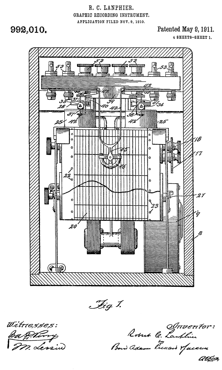
992010 Graphic recording instrument, Robert C Lanphier, Sangamo Electric Co, 1911-05-09, -
Liquid ink on paper with tractor holes.
Parallelogram driven by two meter movements.
The ink pen (7) writes on plain paper.
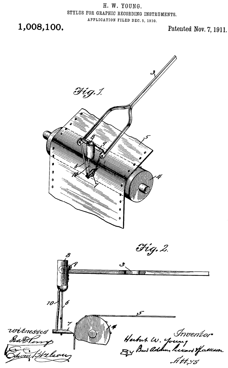
1008100 Stylus for graphic recording instruments, Herbert W Young, Sangamo Electric Co, 1911-11-07, -
1350485 Graphic recording instrument, Jacob W Bard, White Otis, Sangamo Electric Co, 1920-08-24, -
Liquid ink from well by capillary tube.
This has the look and feel of the Type CAN-55070 Range Recorder mentioned in patent 2791756,
but 2791756 writes using a voltage to the stylus.
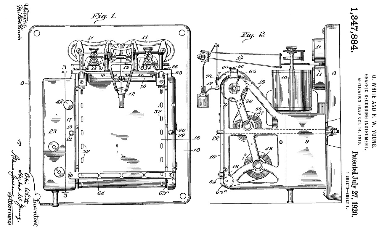
1347884 Graphic recording instrument, White Otis, Herbert W Young, Sangamo Electric Co, 1920-07-27, - very similar to 1350485 above
The paper handling cartridge can be removed as a unit.
The stylus is motor driven from left to right. Dumping electromagnets (11) control when the stylus touches the paper.
2296972 Coated chart paper and method of making same, Earl C Alkire, Emil F Blase, Sangamo Electric Co, 1942-09-29, - "The basic idea or concept of our invention involved in the manufacture of improved coated chart paper is the application of an amorphous pigment coat, such as India ink, to a highly polished non-absorbent surface, such as is provided by a high melting point, hard wax or varnish. This requires that the support paper be given two coatings, the first to provide it with a highly polished surface, and the second to give it a marking surface." - works with a stylus in a manner much the same as a "smoked glass" recording.
Not a voltage on a stylus.
Explains the problems with ink and scratching wax.
Magnavox
Channels - sonar beams
3033955 Electromechanical filter, Steven M Monda, William A Fordeck, Magnavox, 1962-05-08, - remote control TV channel selector uses resonant reeds as audio filters.
3295107 Electronic time compression device, Robert E Stalcup, Magnavox, 1966-12-27, -
3532867 Delay correlator, Luther W Ricketts Jr, Robert E Stalcup, Robert J Erickson, George L Buenger, Magnavox, 1970-10-06, - for comparing time of arrival of two audio signals (like from a pair of hydrophones to determine bearing.
3449711 Beam former, Luther W Ricketts Jr, Robert E Stalcup, Robert J Erickson, Magnavox, 1969-06-10, - for sonar
Fax
3325821 Multispot transducer, Glenn A Reese, Donald H Westermeier, Magnavox, 1967-06-13 - fax printer, uses a ribbon or carbon paper,
3469027 Facsimile transceiver, Facsimile transceiver, Glenn A Reese, Gustavus B Pearson, Magnavox, 1969-09-23, -
3560993 Writing stylus for use in facsimile receiver equipment, Ernest John Okleshen, Magnavox, 1971-02-02, -
3621201 Developer apparatus for heat developing paper, Paul J Crane, Glenn A Reese, Magnavox, 1971-11-16, - "An image developer for heat developing paper, such as dry silver paper, wherein a curved platen is heated by passing a current therethrough, thereby obtaining very quick heating time and very uniform heat."
3611415 Flatbed thermomagnetic facsimile system, Alfred M Nelson, Magnavox, 1971-10-05, - ? relationship to AQA-5?
Thermal Paper (Wiki)
The Signal Data Recorder (SDR) may use thermal paper (Wiki) like the TI Silent 700 printer (Wiki). The patents for the Silent 700 show what amounts to an integrated circuit that contains both the 3x5 dot heating elements and a drive matrix for it.
Electronic Design: The First Handheld Digital Calculator Celebrates 50 Years, Part 2 - Low power Thermal Printing
3501615 Integrated heater element array and drive matrix, Jerry D Merryman, Edward M Ruggiero, TI, 1970-03-17, -
3571917 Integrated heater element array and drive matrix and method of making same, Jerry D Merryman, Edward M Ruggiero, TI, 1971-03-23, -
3601669 Integrated heater element array and drive matrix therefor, Jerry D Merryman, Edward M Ruggiero, TI, 1971-08-24, -


Audio Analysis
The Bell Labs patents prior to 1 Sep 1939 (Wiki: start of W.W.II) where the analysis of speech is the subject I believe are about learning more about speech. But after 7 Dec 1942 when the U.S. is in W.W.II I think any work done on sound, speech or "complex waves" (Code for submarine sounds?) would need to have a tangible benefit related to winning the war rather than some academic theorizing. In that light many of the below patents apply to the sounds made by submarines.
The CRT-1 Sonobuoy and its associated receiver look like conventional audio equipment where the operator wears headphones. But one of the secrets of W.W.II was that waterfall plots were being used in both the frequency and compass bearing modes to learn a lot more than what a submarine sounds like. I expect this was top secret stuff during W.W.II and still now (2021) there's little information available.
To learn about how the AQA-5 made the plot I studied facsimile machines and in particular the Western Union DeskFax. WU Reference 1 mentions the paper: The Sound Spectrograph, W. Koening, H.K. Dunn, L.Y. Lacy, Journal of the Acoustical Society of America, Vol 17, July 1946 (behind a paywall). Why did they make that reference? Hopefully there's a patent for something like the AQA-5. By searching patents for Sound Spectrograph, Bell Labs, Koening, Dunn, Lacy there might be some interesting stuff. Like do any of these patents make use of the WU FAX paper?
When I started this paragraph I was thinking of how the signals from early sonobuoys were processed and displayed to the operator. But this also applies to passive sonar in exactly the same manner. The Wiki page for SONAR/Ocean Surveillance talks about how AT&T used their speech frequency waterfall techniques for SOSUS (Wiki). The Wiki page Low Frequency Analyzer and Recorder (LOFAR) references the Wiki page: Time–frequency analysis. The first generation LOFAR recorders sound like they use the same paper recording method as the Western Union DeskFax machine. They also used an "electromechinacal analyzer" which was replaced by a digital spectrum analyzer in 1963.
"In 1950, spurred by the possibility of a Soviet submarine threat in the Atlantic that would soon surpass that of the World War II German U-boats, Bell Labs initiated a crash program for the Office of Naval Research to develop SOSUS (SOund SUrveillance System), a network of deep ocean long range acoustic sensor arrays to locate, classify, and track Soviet submarines. The SOSUS concept was based on the deep sound channel, or SOFAR (SOund Fixing And Ranging) channel. The low frequency acoustic R&D effort, called Project Jezebel, combined the Bell Labs LOFAR (LOw Frequency Analysis and Recording) equipment with a prototype hydrophone array installed by Western Electric. The SOSUS ocean surveillance program expanded to cover large areas of the Atlantic and Pacific Oceans." (Sonobuoy Ref 6)
It's becoming clear that SOSUS developed the various waterfall displays.
Lofargrams: Frequency waterfall plot.
AN/SQR-17 SONAR Signal Processing Set (Wiki) & Sonobuoy Ref 48: Steel Boats Iron Men - has some info on various versions of the SQR-17.
The AN/TSQ-108(*) Radar Sonar Surveillance Center "van's" are basically a P-3 Orion without wings or torpedoes..( FAS, USNI), nttp-3-10-1.pdf - pg50 -
AQA-nTime Line
The United States Navy Film Catalog, NAVWEPS 10-1-777, 1 May 1966 - lists AQA-1
This gives an overview of the technology of 1966.
(pg 9)
DETECTION SYSTEMS
MN-8497 Explosive Echo- Ranging ASW
MN-8803A Anti -Submarine Warfare - Indicator Group An /AQA - 3 (Jezebel)
MB - 9431 Sight Unseen
MB-9435A Julie — Part 1 Basic Mechanics and Tactics
MB- 9435B Julie - Part 2 – Tactical Procedures
(pg 18)
RADIO SONO BUOYS
MN-2404D Underwater Detection Gear - Installing Sono-Radio Buoys
MN-8321A The Sonobuoy Indicator Group - AN /AQA - 1 --Operation
(pg 165)
RADIO SONO BUOYS
MN-2404D Underwater Detection Gear - Installing Sono- Radio Buoys
MN - 6988A The Listening Sonobuoy - Application and Operation
MN-6988B The Listening Sonobuoy — Testing
MN-8321A The Sonobuoy Indicator Group - AN /AQA - 1 - Operation
SCANNING SONAR
MN - 8593A Sonar Systems for Submarines — Principles of Operation — AN /BQS- 2 Scanning Sonar
MN - 8593D Sonar Systems for Submarines — Principles of Operation of AN /BQS - 4, 4A Sonar Sets
MN - 8919 Operation of the Sonar Set AN /AQS - 10
MN - 9222A Sonar Systems for Surface Ships - Azimuth Scanning Sonar— Principles of Operation
MN-9519A AN /SQS - 4 (RDT) Sonar — Controls (DCNO-(FR ) -1-59 Film Training Aid )
MN-9536H AN /BQQ - 2 Integrated Sonar System Sonar Receiving Set AN /BQQ - 2
SIGNAL ANALYSIS
MN-7903A Classification of Contacts by Anti-Submarine Ships — Audio Characteristics
MN-7903B Classification of Contacts by Anti -Submarine Ships — Visual Characteristics
MN-79030 Classification of Contacts by Anti-Submarine Ships — Coordination of Classification Data
MN-7903D Classification of Contacts by Anti-Submarine Ships— Teamwork in Classification
MN-7931 Acoustic System Mark 6 in Harbor Defense
FN-8100A Sonar Contact Classification Part 1 – Submarine Contacts at Various Aspects
FN-8100B Sonar Contact Classification Part 2 — Whale and Reef Contacts
FN - 81000 Sonar Contact Classification Part 3 — Wake and Bottom Contacts
FN - 8100D Sonar Contact Classification Intermediate Interference
FN-8100E Sonar Contact Classification Submarine and Torpedo Contacts
FN-8100F Sonar Contact Classification - Intermediate Effects of MK 14 Depth Charge
FN-8100G Sonar Basic Contact Classification Test - Kit 9
FN-8100H Sonar Target Classification - Demonstration and Drills — Kit 10 — Part 1 -A
FN-81001 Sonar Target Classification - Demonstration and Drills - Kit 10 — Part 1 - B
FN -8100 Sonar Target Classification - Demonstration and Drills — Kit 10 — Part 2-A
FN-8100K Sonar Target Classification - Demonstration and Drills — Kit 10 — Part 2-B
FN - 8100L Sonar Target Classification Demonstration and Drills — Kit 10 — Part 3-A
FN-8100M Sonar Target Classification - Demonstration and Drills — Kit 10 — Part 3-B
MN-8100N Sonar Contact Classification - Situational Test - Kit 11 A
MN-81000 Sonar Contact Classification - Situational Test-Kit 11B
MN-8856 ASW Sonar Target Classification - Using RDT — Modified AN /SQS - 4 Sonar
MN - 9500A Bupers Technical Film Report Pers 2–60 — SQS - 4 Echo Recognition
MN-9500B Bupers Technical Film Report Pers 3–60 — SQS – 4 Echo Recognition
MN-9500C Bupers Technical Film Report Pers 4–60—SQS-4 Echo Recognition
MN-9500D Bupers Technical Film Report Pers 5–60 — SQS– 4 Echo Recognition
MN-9500E Bupers Technical Film Report Pers 6–60 — Exercises in Sonar Target Classification
MN-9500F Bupers Technical Film Report Pers 7–60 — Exercises in Sonar Target Classification
MN-9500G Bupers Technical Film Report Pers 8–60 — Exercises in Sonar Target Classification
MN - 9500H Bupers Technical Film Report Pers 9–60 — Exercises in Sonar Target Classification
MN-95001 Bupers Technical Film Report Pers 10–60 — Exercises in Sonar Target Classification
MN-9500J Bupers Technical Film Report Pers 11-60 — Exercises in Sonar Target Classification
MN-9500K Bupers Technical Film Report Pers 12–60 - Exercises in Sonar Target Classification
MC-9923A AN /SQS - 23 Sonar Target Classification MC-9923B AN /SQS - 23 Sonar Target Classification
MC-99230 AN /SQS– 23 Sonar Target Classification MC-9923D AN /SQS- 23 Sonar Target Classification
MC-9923E AN /SQS- 23 Sonar Target Classification MC-9923F AN /SQS- 23 Sonar Target Classification
(pg 166)
SONAR CLASSIFICATION
MN-9536G AN /BQQ-2 Integrated Sonar System — AN /BQQ - 3 Classification Set (
SONAR EQUIPMENT
MN-9536A Integrated Sonar System - AN /BQQ - 2 — Introduction
MN-9536E Computer Indicator Set - AN /BQA - 3 — Integrated Sonar System - AN /BQQ - 2
MN - 9744 AN /SQS – 26 Sonar Set - Operation
MN-9845 Variable Depth Sonar - Introduction SONAR PLOTTING
MN - 84870 Submarine Tactics — Sonar Plotting Techniques — Part 1
MN - 8487D Submarine Tactics — Sonar Plotting Techniques — Part 2 SONAR RECEIVERS
MN-8593B Sonar System for Submarines — Principles of Operation — AN /BQR - 2B Listening Sonar
MN-9536B AN /BQQ - 2 Integrated Sonar System — Sonar Receiving Set - AN / BQR - 7 SONAR SOUND ANALYZERS
MN - 85930 Sonar Systems for Submarines — Azimuth Recorders - Adjustment and Operation TURN COUNTING
FN-8561A Submarine Sonar Turn Counting, Basic Kit No. 2 — Session 1 – Introduction and Demonstration
FN-8561B Submarine Sonar Turn Counting, Basic Kit No. 2_Session 2 — Elementary Drill
FN - 85610 Submarine Sonar Turn Counting, Basic Kit No. 2 — Session 3 — Intermediate Drill
FN-8561D Submarine Sonar Turn Counting, Basic Kit No. 2_Session 4 – Situational Drill
UNDERWATER OBJECT LOCATORS
MN-9416 Sonar Detecting Ranging Set AN /PQS- 1 - Operation
(pg 167)
UNDERWATER SOUND
MN-8857 Introduction to Underwater Sound
MN-8998F Physics of Underwater Sound — Part 1 – Basic Principles
MN-89986 Physics of Underwater Sound — Part 2 — Velocity Profiles
MN - 8998H Physics of Underwater Sound - Part 3 — Absorption and Scattering
MN - 9949 Environmental Effects of Underwater Sound
(pg 180)
RADIO SONO BUOYS
MN-2404D Underwater Detection Gear - Installing Sono- Radio Buoys
MN - 6988A The Listening Sonobuoy - Application and Operation
MN-6988B The Listening Sonobuoy — Testing
MN-8321A The Sonobuoy Indicator Group - AN /AQA - 1 - "Operational controls and adjustments. Use with echo -ranging sonobuoys, directional and non-directional listening sonobuoys. Establishment of target fix."
(pg 516)
MN-8803A ANTI-SUBMARINE WARFARE — INDICATOR GROUP AN/AQA- (1) ( JEZEBEL )
Aircraft electronic system to detect, identify, and locate submerged submarine. How it works.
(pg 573)
MN-9536E COMPUTER INDICATOR SET- AN /BQA-3 — INTEGRATED SONAR SYSTEM - AN /BQQ-2
C4 DIST L 64 REL XX B&W SND 15 MIN BUSHIPSTime Line
1966 Defense Ind Bulletin, pg44 -Bendix Corp., Baltimore, Md. $1,776,045. Components for the AN/AQA-5 indicator group used in P-3A aircraft.
Implementation of the U.S. Arms Embargo... 1973:
Electronics and Equipment: (P-3A/B): communications and navigation equipment comprises
two ARC-94 HF tranceivers,
ARC-84 VHF transmitter, two ARC-84 VHF receivers,
two ARC 51A UHF transceivers,
AIC-22 interphone,
TT-264/AG teletypewriter,
UNH-6 communications tape recorder,
two CU-351 HF couplers,
ASN-42 inertial navigation system,
APN-153 Doppler navigation system
ASA-47 Doppler air mass computer,
ASN-50 AHRS,
APN-70 LORAN,
ARN-52 TACAN,
DF-202 radio compass,
ARN-32 marker beacon receiver,
APN-141 radar altimeter,
ARA-25A UHF direction finder,
two NVA-22A VOR installations,
two HSI, A/A24G-9 true airspeed computer,
PB-20N autopilot,
ID-888/U latitude/longitude indicator, and APQ-107 radar altitude warning system,
ASW equipment includes:
ASA-16 tactical display,
two APS-80 radar antennae for 360 degree coverage,
APA-125A radar display,
ASR-3 trail detector,
two ARR-52A sonobuoy signal receivers,
AQA-1 sonobuoy indicator,
AQA-5 sonobuoy indicator (Jezebel),
ASA-20A sonobuoy recorder (Julie),
ASQ-10A magnetic anomaly detector in plastic tail "sting",
modified ALD-2B ECM direction finder for detecting and locating electronic emissions from submarines,
ULA-2 ECM signal analyser,
APX-6 IFF identification, APX-7 IFF recognition, APA-89 IFF coder group,
AQH-1(V) tactical tape recorder,
ASA-50 ground speed and bearing computer,
R-1047/A op-top position indicator,
TD-441/A intervalometer,
PT396/AS ground track plotter,
ASA-13 tactical plot board, bearing-distance-heading indicator and K7 364 video decoder.
Equipment for day or night photographic reconnaissance.
Search-light under starboard wing.
Electronics and Equipment (P-3C):
ASW Equipment:
two ARR-72 sono receivers,
two AQA-7 DIFAR sonobuoy indicator sets,
hyperbolic fix unit;
acoustic source signal generator (Mk 84?)
time code generator and AQH-4(V) sonar tape recorder;
ASQ-81 magnetic anomaly detector; ASA-64 submarine anomaly detector, ASA-65 magnetic compensator;
ALQ-78 electronic countermeasures set;
APS-115 radar set (160 degree coverage);
ASA-69 radar can converter;
AXR-13 low light level television (displayed on both ASA-70s);
KA-74 forward computer-assisted camera; KB-18A automatic strike assessment camera with horizon-to-horizon coverage;
RO-308 bathytheremograph recorder.
Audio Analysis Patents
1654068 Apparatus for the visual interpretation of speech and music, David G Blattner, Western Electric, 1927-12-27, - Three Color Organ (Wiki: Mechanical, Electric) - 0-410, 410-520 & 800 -up Hz filters, driving light bulbs.
1678674 Method and apparatus for computation, Jr Walter Koenig, AT&T, 1928-07-31, - manual harmonic analysis
1977997 Control system, Patterson Edward Bell, RCA, 1934-10-23, - sound to control lights
1994232 Wave analyzer, Jr Oscar H Schuck, 1935-03-12, - microphone, filters, motor, CRT, cited by 50 patents.
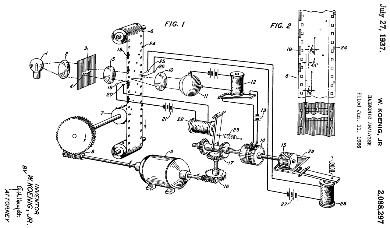
2088297 Harmonic analyzer, Jr Walter Koenig, Bell Labs,1937-07-27, -
Designed to analyze a non-sinusoidal curve to find its sine and cosine components, i.e. do an FFT.
2144844 Magnetic telegraphone, Clarence N Hickman, Bell Labs, 1939-01-24, -see Magnetic Recording
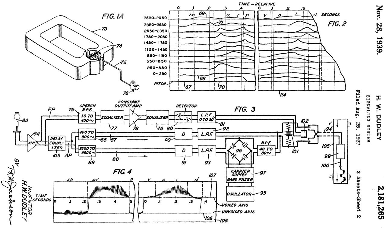
2181265 Signaling system, Homer W Dudley, Bell Labs, 1939-11-28, -
Aimed at breaking voice into bands and plotting amplitude of each using a plethora of pen recorders.
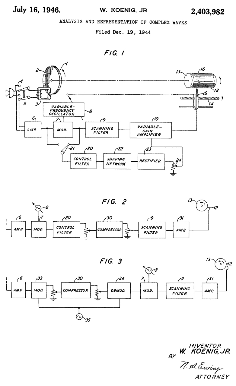
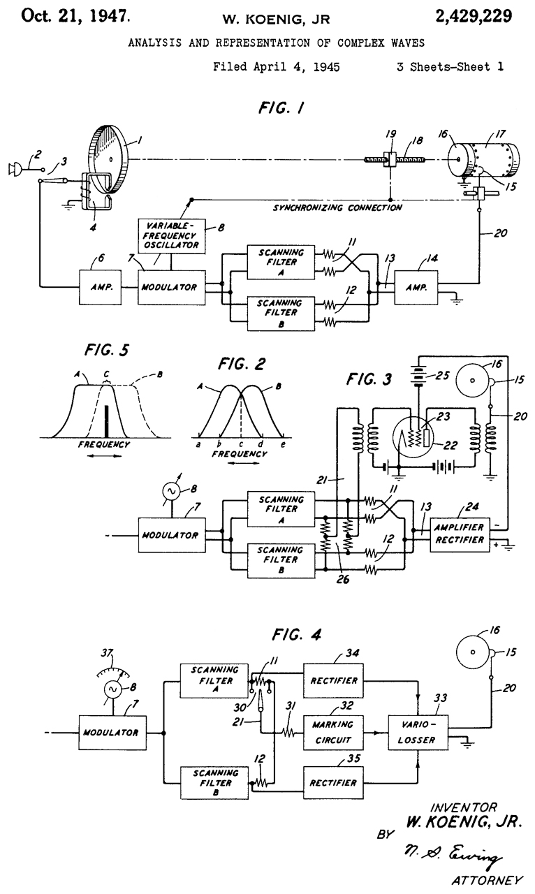
2403982 Analysis and representation of complex waves, Jr Walter Koenig, Bell Labs, App:1944-12-19, Pub: 1946-07-16, -
mentions Teledeltos Grade H facsimile paper
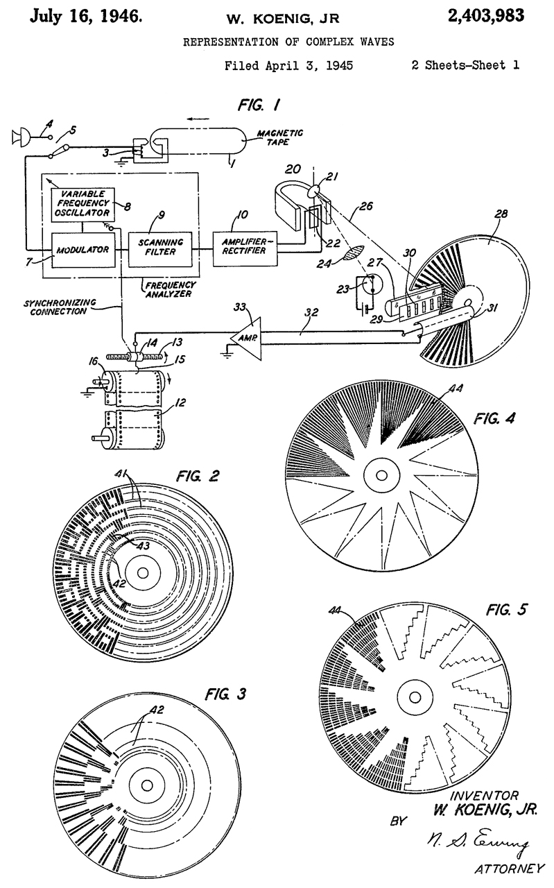
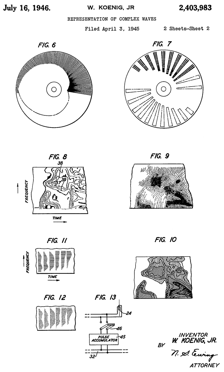
2403983 Representation of complex waves, Jr Walter Koenig, Bell Labs, App:1945-04-03, Pub 1946-07-16 -
Contains Frequency - Time plots (Waterfall).
"...marking current to a recording stylus."
an endless moving belt of sensitized paper (12) 'Teledeltos Grade H' facsimile paper
cited by 21 patents
mentions Teledeltos
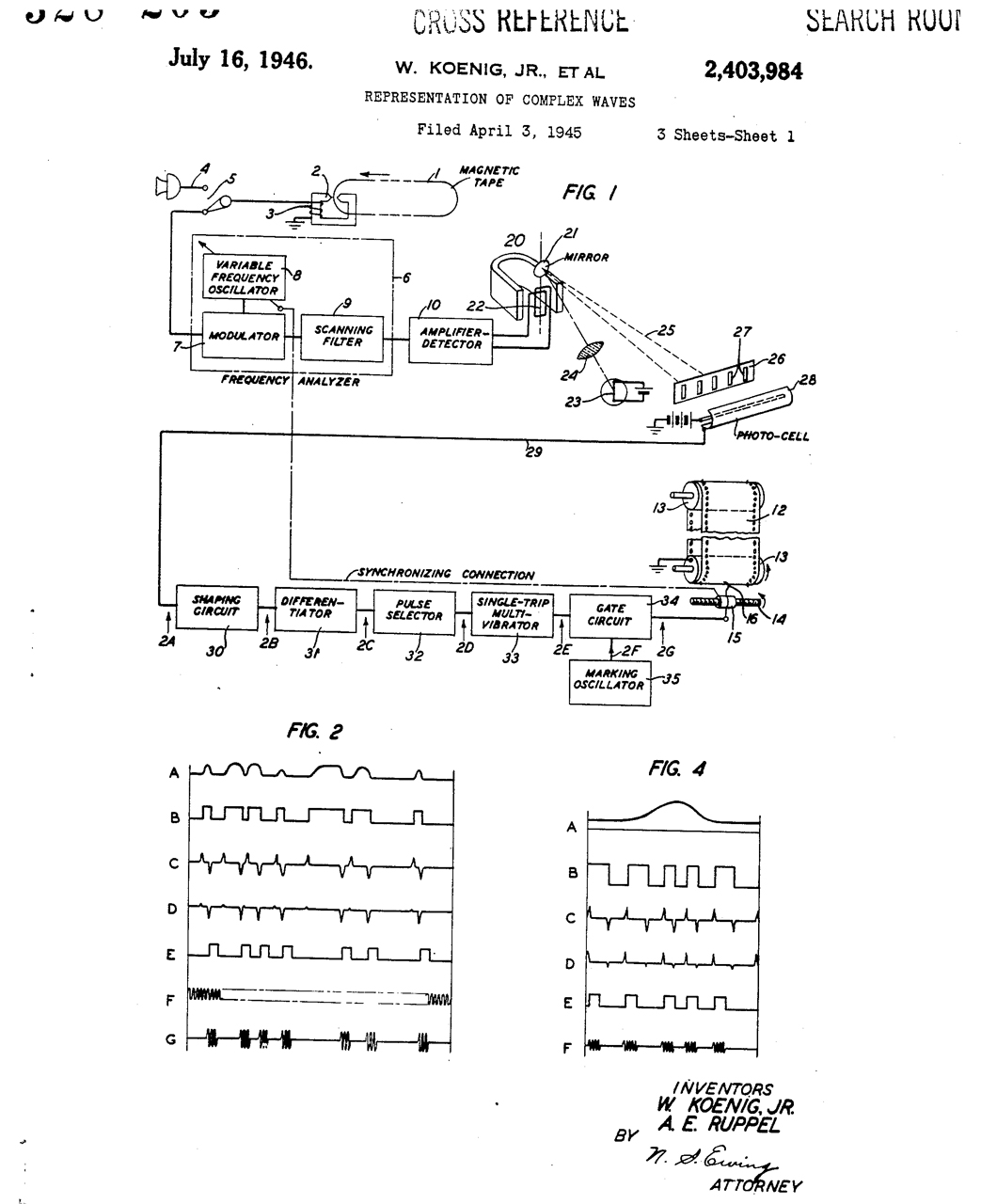
2403984 Representation of complex waves, Jr Walter Koenig, Alfred E Ruppel, Bell Labs, App: 1945-04-03, Pub: 1946-07-16, 704/276; 346/33M; 327/172; 324/76.13 - refinements to the prior system.
mentions Teledeltos
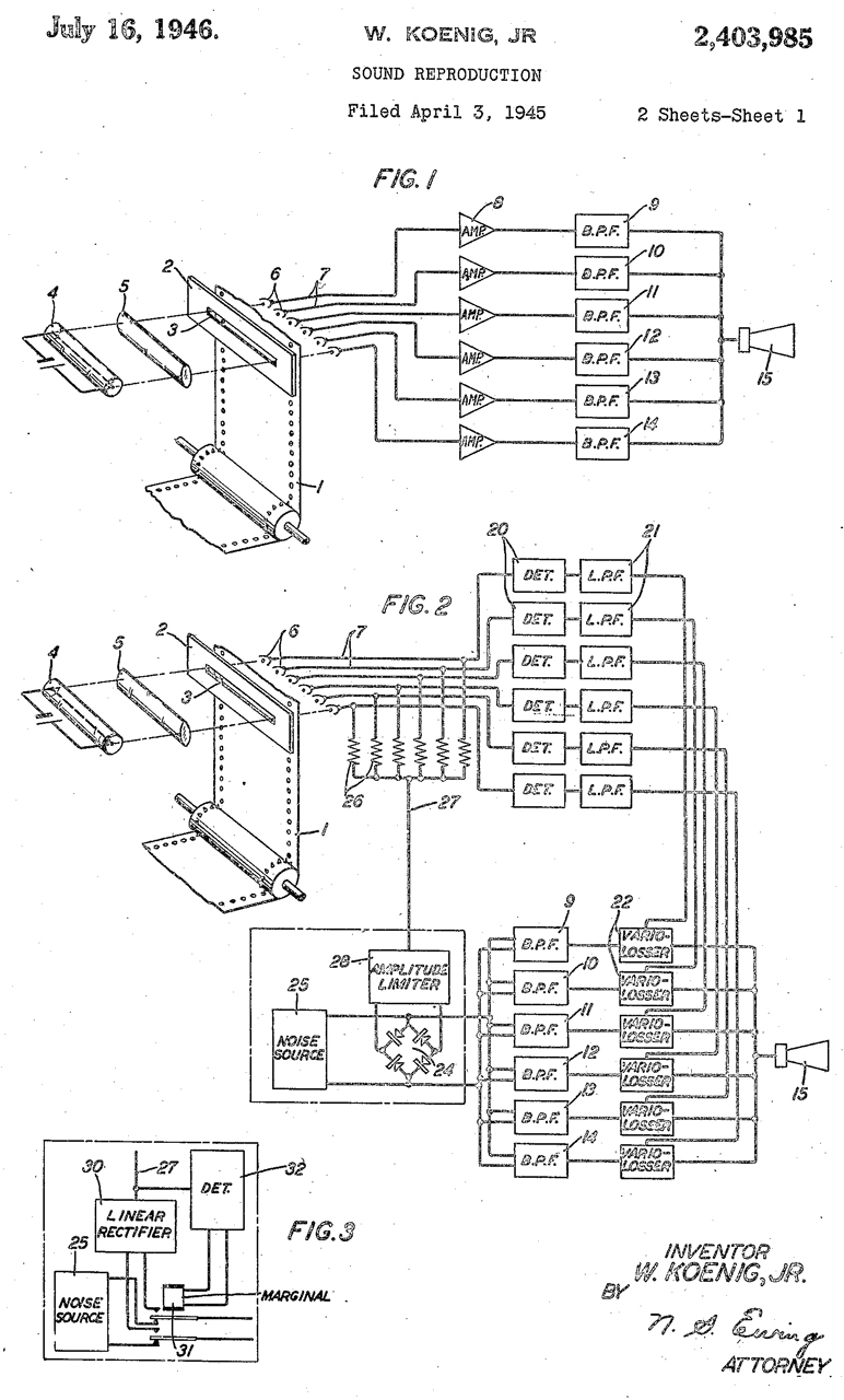
2403985 Sound reproduction, Jr Walter Koenig, Bell Labs, App: 1945-04-03, Pub: 1945-04-03, Pub: 1946-07-16, - "...the reproduction of Speech waves from a speech Spectrogram.
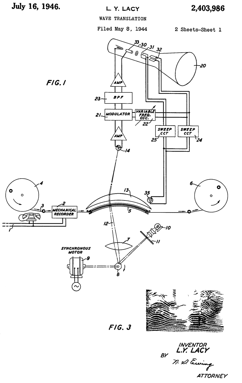
2403986 Wave translation, Lester Y Lacy, Bell Labs, App: 1944-05-08, Pub: 1945-04-03, Pub: 1946-07-16, -
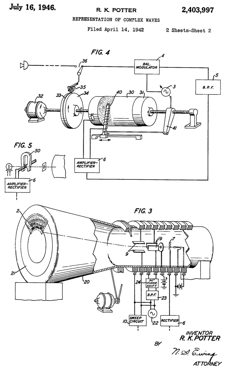
2403997 Representation of complex waves, Ralph K Potter, Bell Labs, App: 1942-04-14, Pub: 1946-07-16 -
mentions Teledeltos Grade H facsimile paper
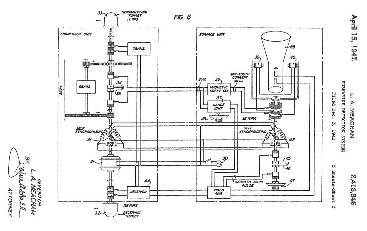
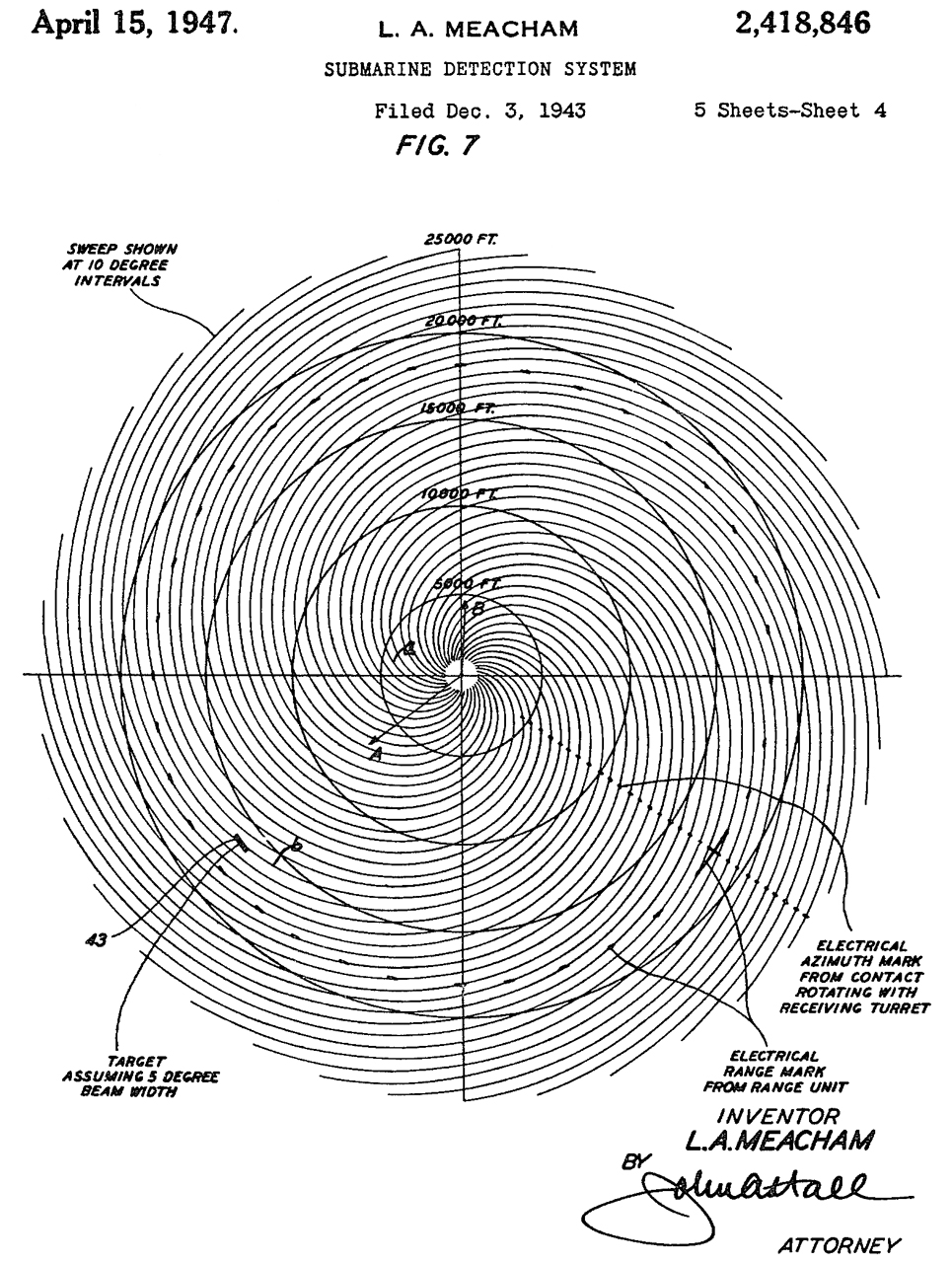
2418846 Submarine detection system, Larned A Meacham, Bell Labs, App:1943-12-03, Pub: 1947-04-15, -
Tx hydrophone beam rotates 1 Rev per Second, Rx hydrophone beam rotates 36 Rev per Second.
same inventor as 3021478
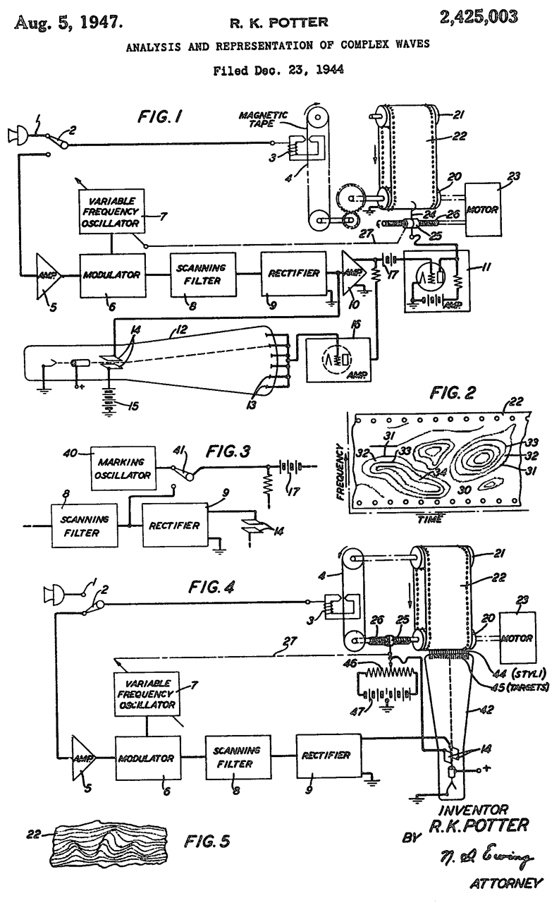
2425003 Analysis and representation of complex waves, Ralph K Potter, Bell Labs, App: 1944-12-23, Pub: 1947-08-05, -
mentions Teledeltos Grade H facsimile paper
2429229 Analysis and representation of complex waves, Jr Walter Koenig, Bell Labs, App: 1945-04-04, Pub: 1947-10-21, -
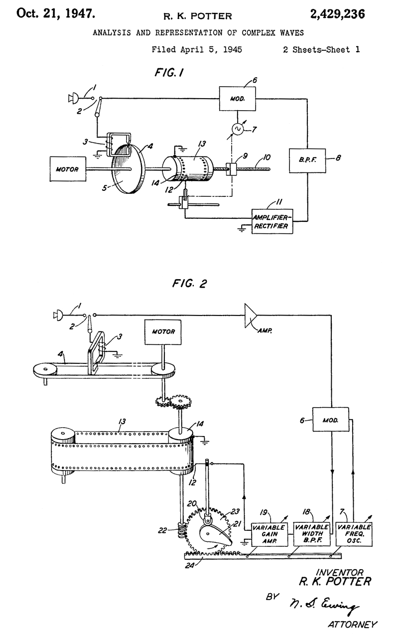
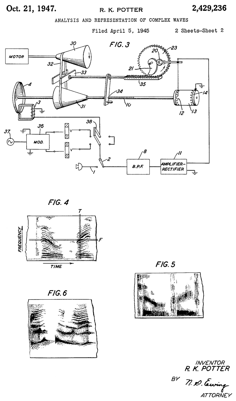
2429236 Analysis and representation of complex waves, Ralph K Potter, Bell Labs, App: 1945-04-05, Pub: 1947-10-21, -
mentions Teledeltos Grade H facsimile paper
Time v. Frequency plot
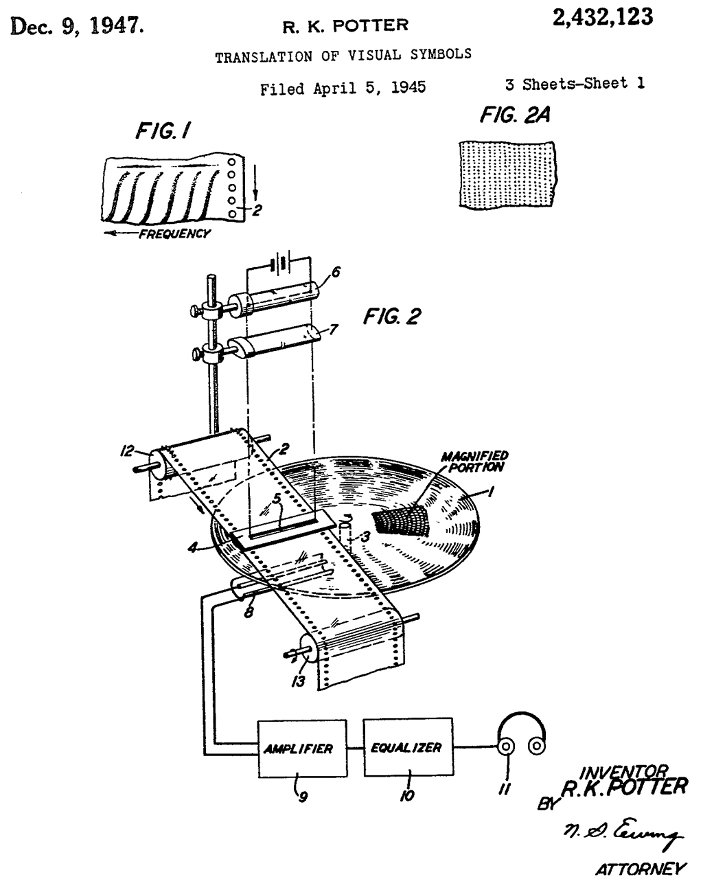
2432123 Translation of visual symbols, Ralph K Potter, Bell Labs, App: 1945-04-05, Pub: 1947-12-09, -
stated goal is to turn a spectrogram back into speech, i.e. an inverse spectrogram.
There are current software packages that attempt to do this but it's difficult because phase information is lost in making the spectrogram and so is not there to recover. So some guessing and trial and error is involved.
A wild guess is that this might be a way to analyze a spectrogram made from a submarine sound.
2463535 Electron discharge device, Hecht George, Bell Labs,1949-03-08, - vocoder, not subs
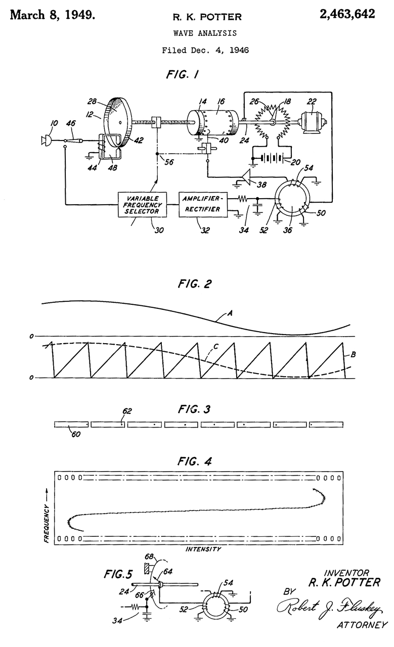
2463642 Wave analysis, Ralph K Potter, Bell Labs, App: 1946-12-04, Pub: 1949-03-08, -
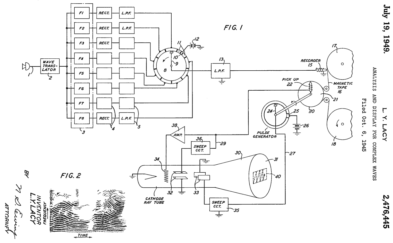
2476445 Analysis and display for complex waves, Lester Y Lacy, Bell Labs, App:1945-10-06, Pub: 1949-07-19, -
This is a classical parallel filter method. At this time audio recording was done on flat phonograph disks.
I had one of the recording turntables and it used a lead screw to move the cutting arm.
Tape recorders came from Germany after W.W.II.
There were some wire recorders not sure of the timing but expect it was late 1950s early 1960s.
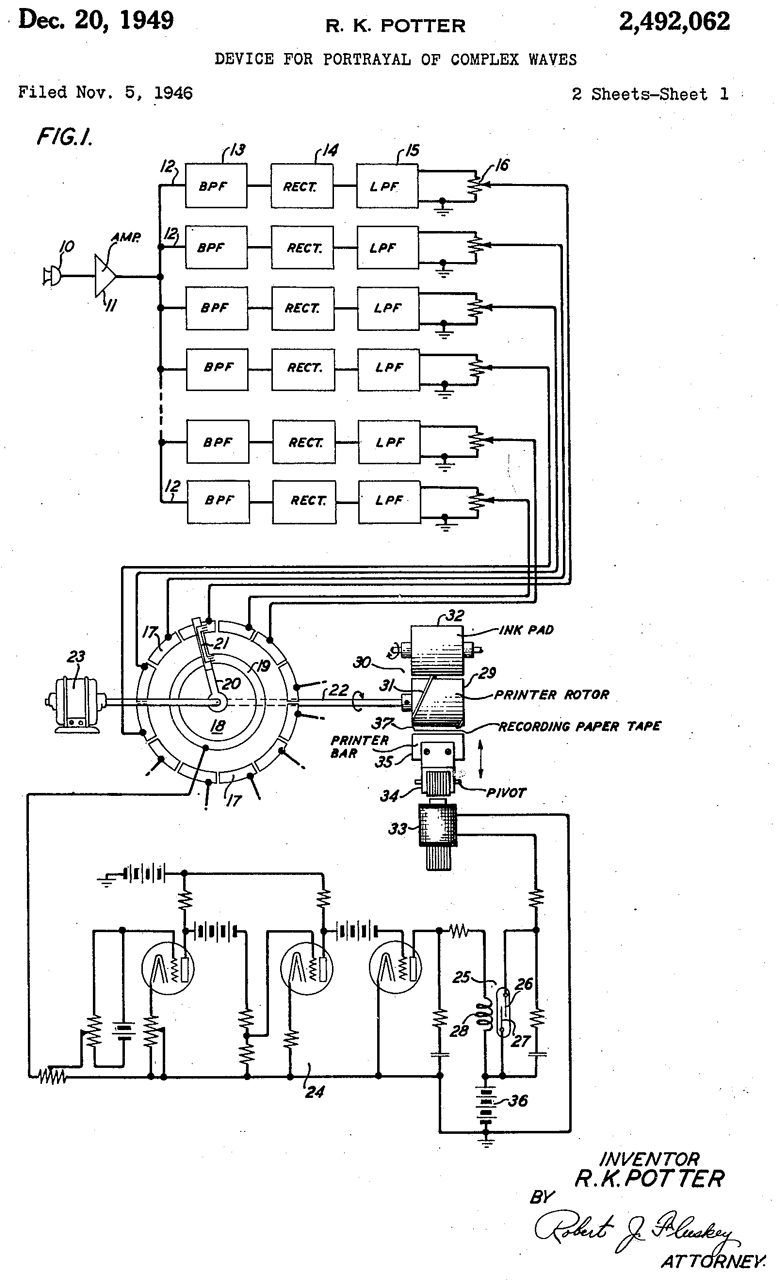
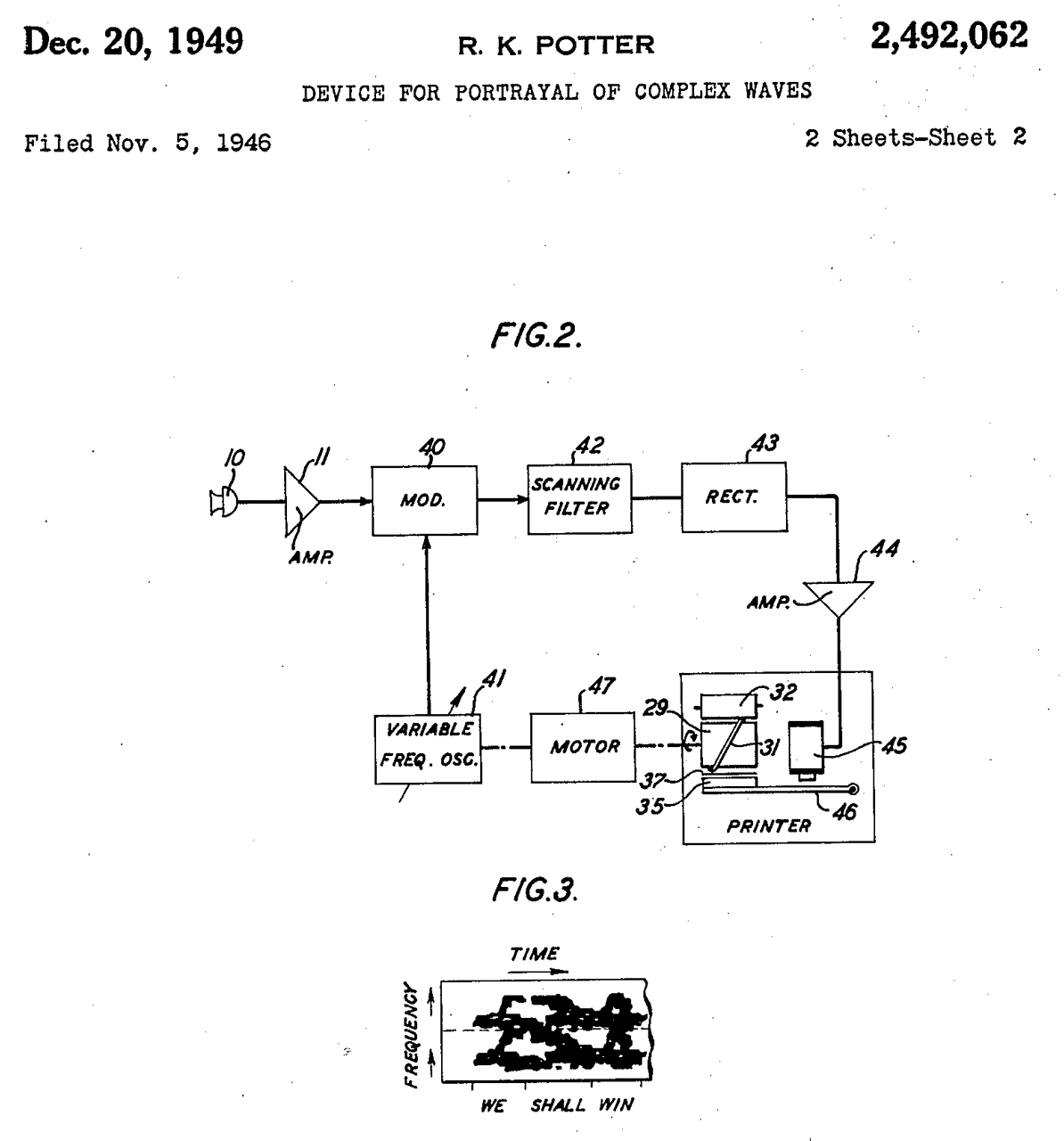
2492062 Device for portrayal of complex waves, Ralph K Potter, Bell Labs, App: 1946-11-05, Pub: 1949-12-20, -
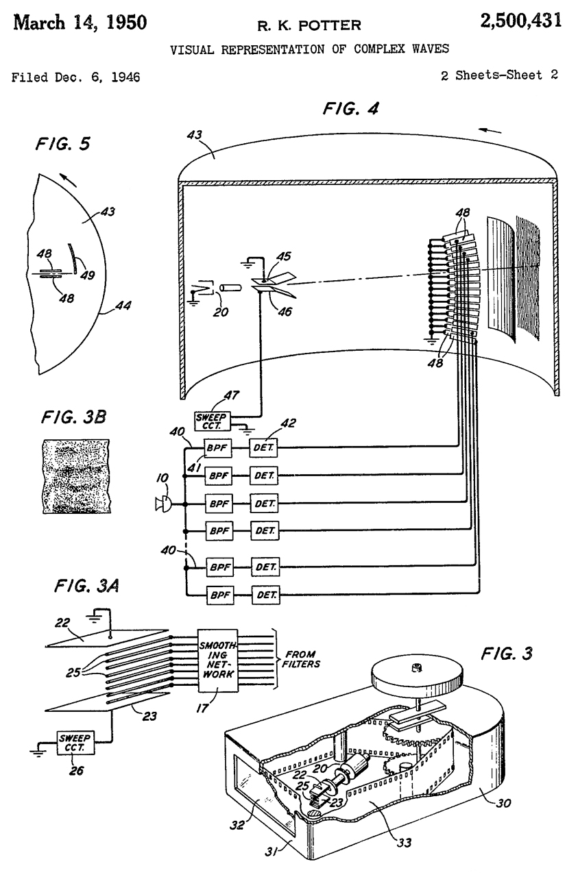
2500431 2500431 Visual representation of complex waves, Ralph K Potter, Bell Labs, App: 1946-12-06, Pub: 1950-03-14, - makes use of a custom CRT.
Note this predates the RCA Graphechon.
2507525 Panoramic system, Hurvitz Hyman, Panoramic Radio Corp, 1950-05-16, -
2532731 Visualization of complex waves, Ralph K Potter, Bell Labs, App: 1946-12-28, W.W.II, Pub: 1950-12-05, -
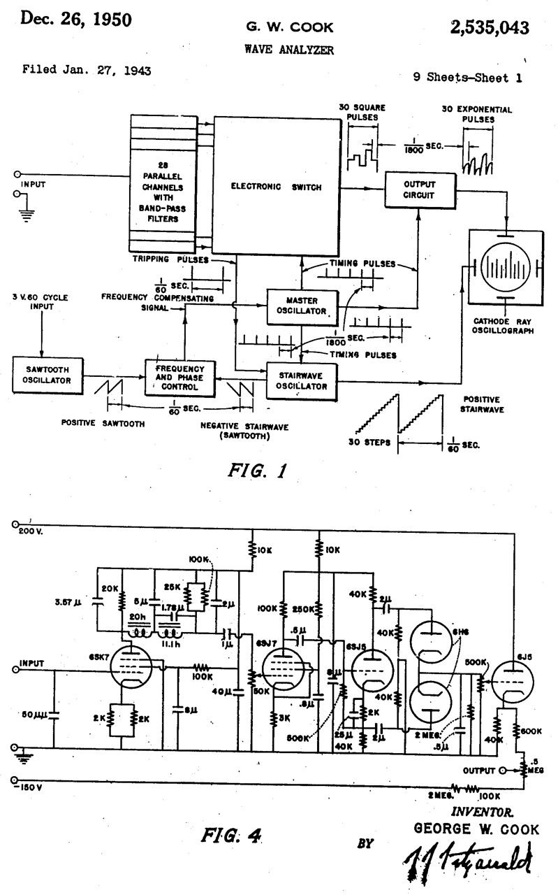
2535043 Wave analyzer, George W Cook, App: 1943-01-27, TOP SECRET, Pub: 1950-12-26, - This is probably very big, heavy and consumes a lot of power.
2561478 Analyzing system for determining the fundamental frequency of a complex wave, Mitchell Doren, Bell Labs, App: 1948-05-28, Pub: 1951-07-24, -
for speech transmission, not subs
2570858 Frequency analyzer, Jan A Rajchman, RCA, App: 1949-02-26, Pub: 1951-10-09, -
This is a few years ahead of the Graphechon, see below.
Cites 2403997 & 2403986
2590809 Variable selectivity panoramic system, Wallace Marcel, 1952-03-25, - CRT based
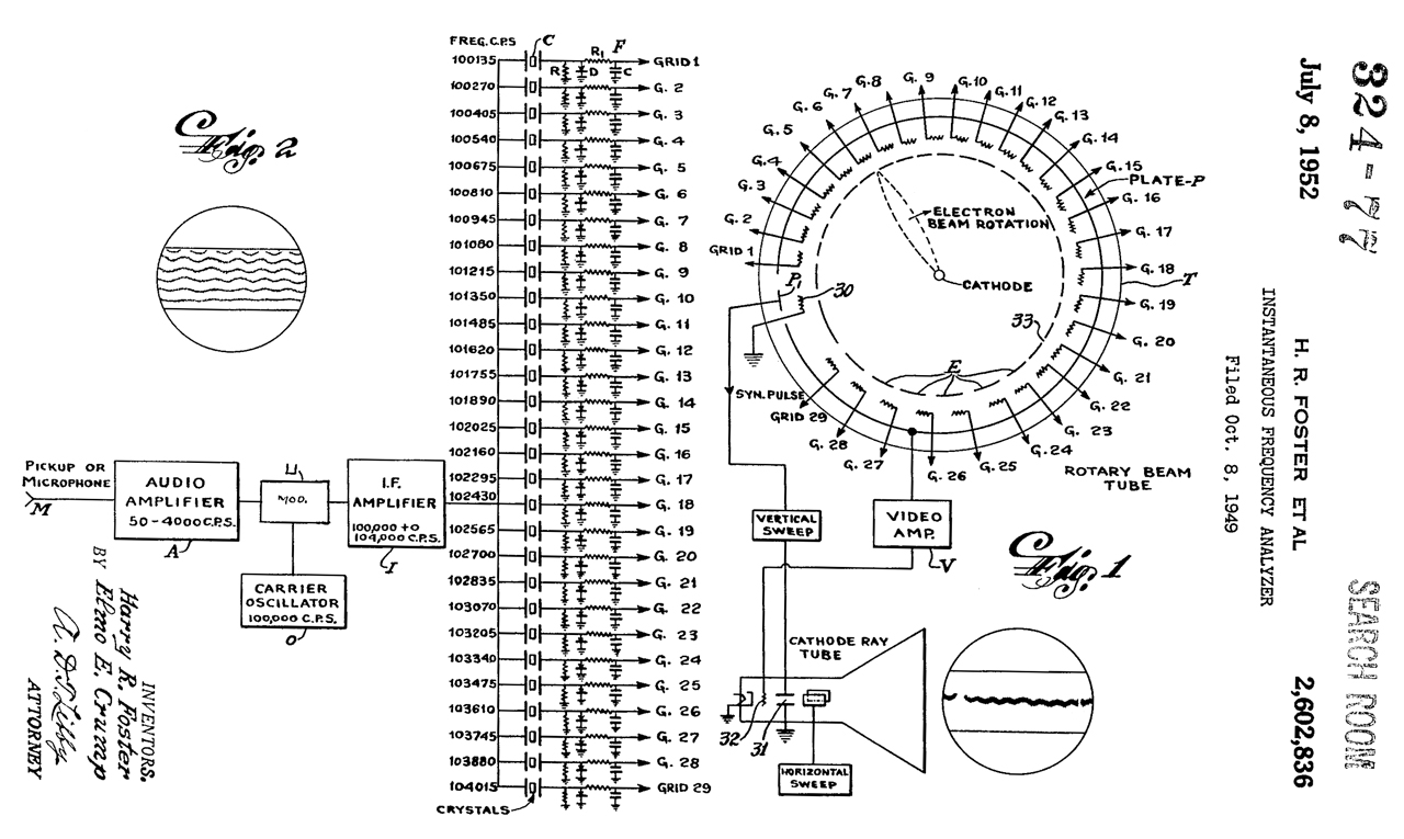
2602836 Instantaneous (audio) frequency analyzer, Harry R Foster, Elmo E Crump, Ohmega Lab, 1952-07-08, 324/76.29; 704/276; 324/76.19; 324/76.68; 324/76.44 - Kay Vibralyzer? (Wiki: Donald J. Borror)
YouTube: The Singing Life of Birds (with sonograms)
2615078 Frequency analyzer system, Harry R Foster, Elmo E Crump, Ohmega Lab, 1952-10-21, -
Sensitized paper (responds to voltage) (P) mounted on drum (D).
Circular table (T) with magnetic film (A) as a recording surface.
The sound to be analyzed is recorded then over hundreds of revolutions is played back through narrow band filters and the output written on the paper (P) by the finger (F) as it is moved by a lead screw.
The problem is to keep the high voltage (150 VDC) from getting back into the record/playback head (H). "putting an impedance preferably in a form of a suitable resistance of about 100 ohms connected between the head H and ground, that this reduced the interference sufficiently to eliminate all of the trouble of a ground at the shaft bearing which is still retained to take as much of the current coming from F as possible."
2632036 Panoramic recorder, Hurvitz Hyman, 1953-03-17, - for audio spectrum
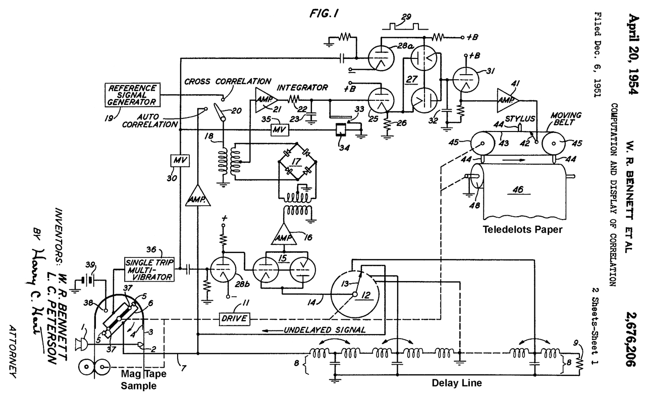
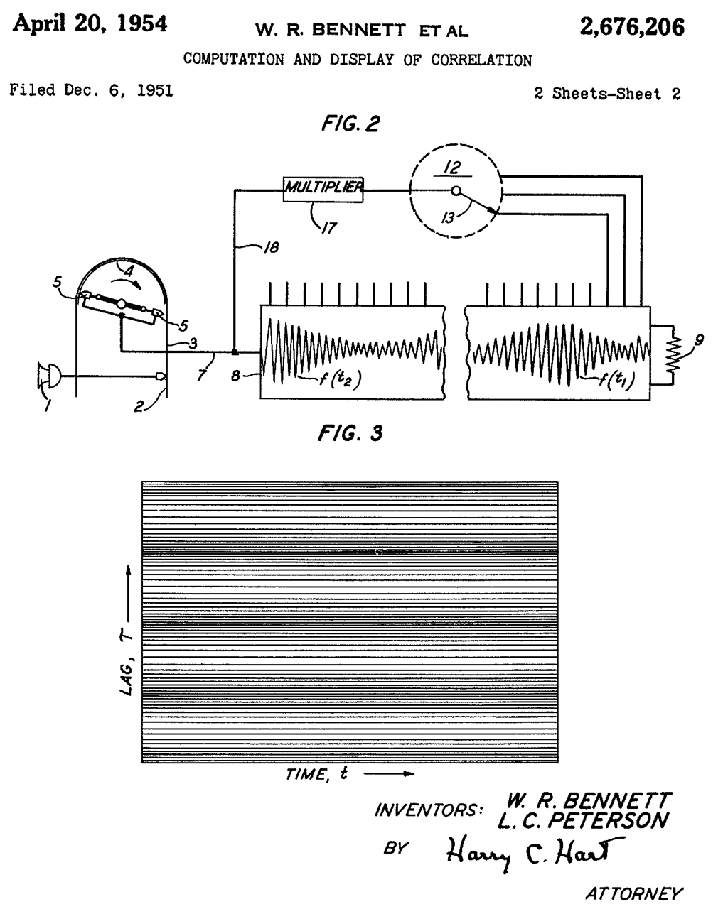
2676206 Computation and display of correlation, William R Bennett, Liss C Peterson, Bell Labs, 1954-04-20, -
"There exist, however, signals which naturally appear in the form of a pulse or a sequence of pulses, and there exist circumstances under which the time relations of such phenomena, are of much greater interest than their frequencies. In such cases analysis of signals by way of the correlation approach is more expedient ... than Spectrum analysis." I'm guessing this may apply to things like a ship's propeller beat as heard from a sonobuoy or passive sonar.
mentions Teledeltos
2680228 Optimum filter for detecting and differentiating complex signals, Caldwell P Smith, Air Force, 1954-06-01, -
The filters go to 6 kHz, way above human speech, why?
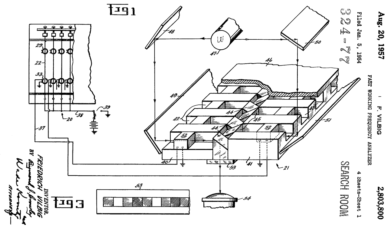
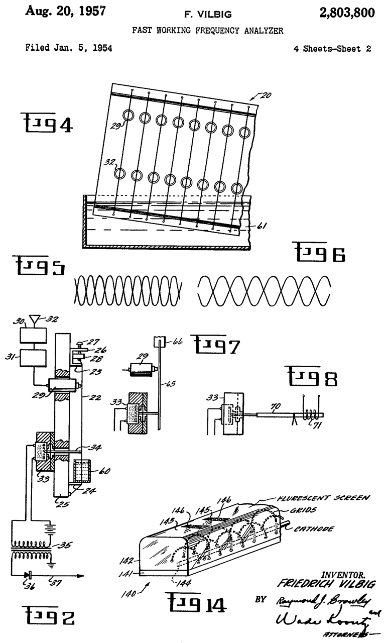
2803800 Fast Working Frequency Analyzer, Friedrich Vilbig, Air Force, App: 1954-01-05, Pub: 1957-08-20, - Many steel strings (like on a guitar) are tuned to different frequencies and excited by electromagnets and sensed by other electromagnets.
My guess is that this might work in a lab when mounted on a concrete pillar, but it would be very challenging to get it to work in an environment with shock and noise, line an aircraft.
2804500 Color interpretation system, Lawrence J Giacoletto, RCA, 1957-08-27, - music into color patterns - mod to color TV
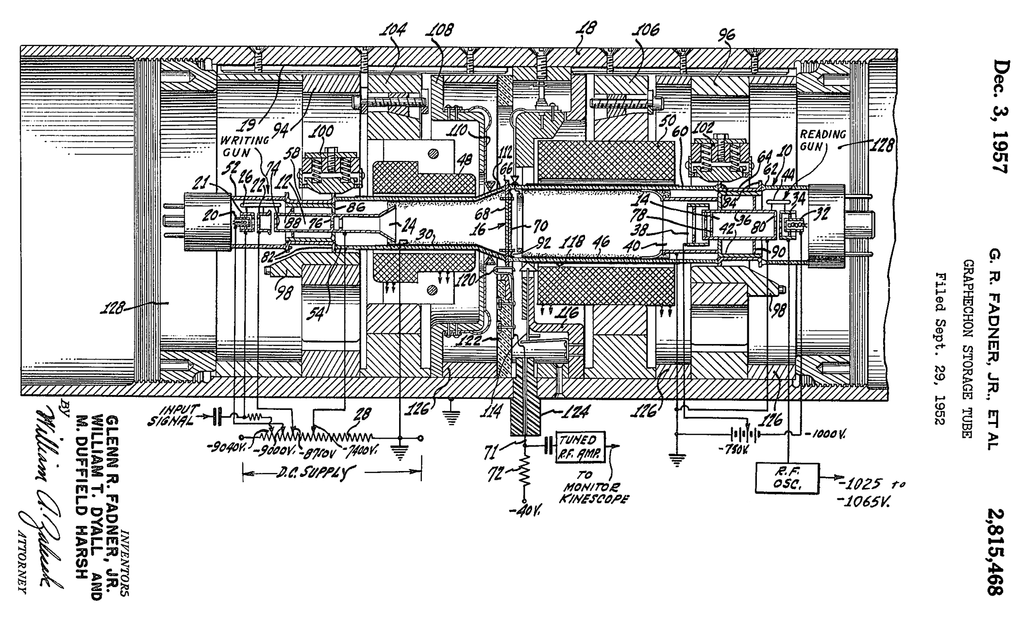
2815468 Graphechon storage tube, Jr Glenn R Fadner, William T Dyall, Harsh Maurice Duffield, NAVY, App: 1952-09-29, Pub: 1957-12-03
This is a much better way of storing a sample for spectrograph signal processing than the prior mechanical magnetic recording methods.
Note: assigned to Navy not RCA.
part of the Hazeltine 3617883 patent.
2890091 Ultra high speed level recorder, Westley F Curtis, App: 1955-03-04, Pub: 1959-06-09, - multiple styli recorder with no moving parts.
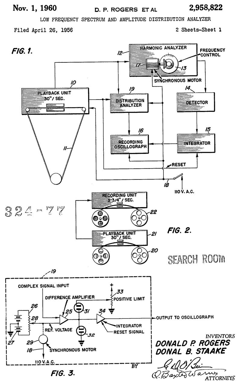
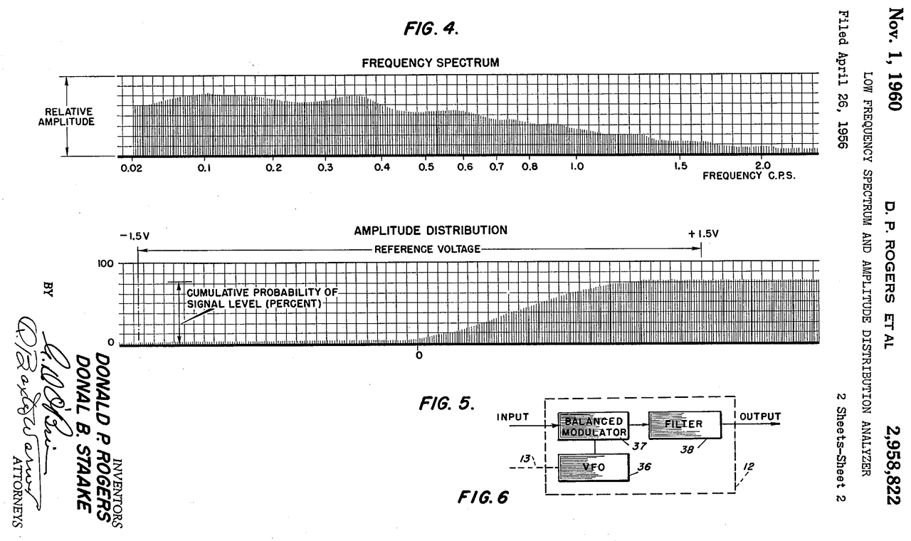
2958822 Low frequency spectrum and amplitude distribution analyzer, Donald P Rogers, Donal B Staake, Navy, App: 1956-04-26, Pub: 1960-11-01, -
0.02 to 2.0 Hz spectrum analysis.
One way is to tape record at 3-3/4 IPS and play back at 30 IPS, giving an 8X frequency multiplication.
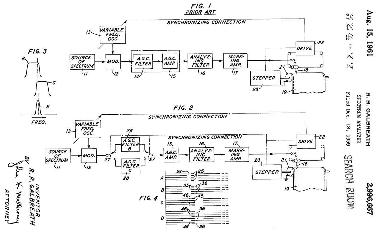
2996667 Spectrum analyzer, Robert R Galbreath, Bell Labs, 1961-08-15, -
Uses AGC filters with different bandwidths on alternate sweeps of the AQA-5 to improve dynamic range.
Also see: 4628255
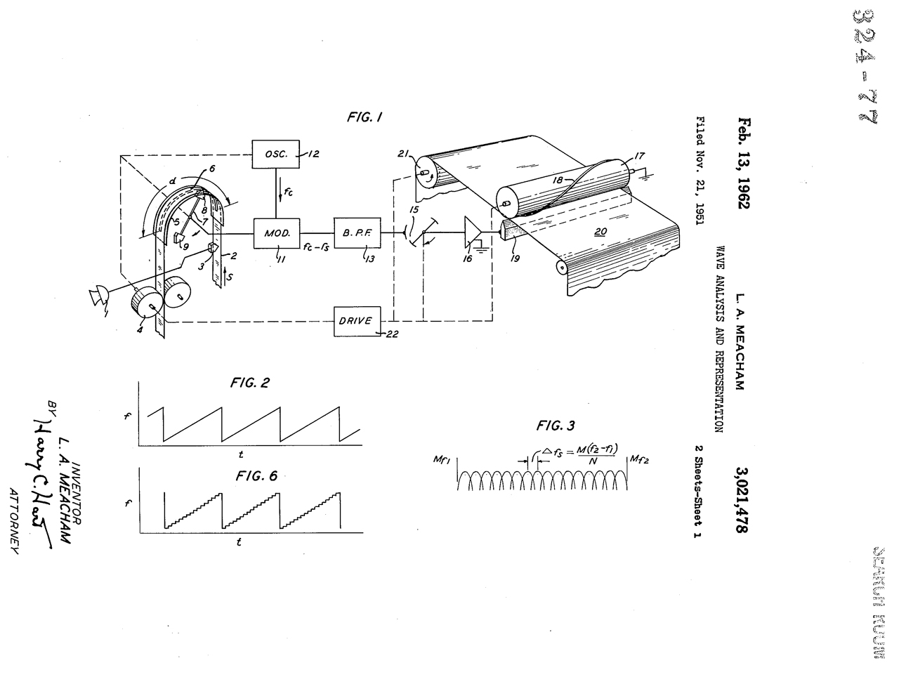
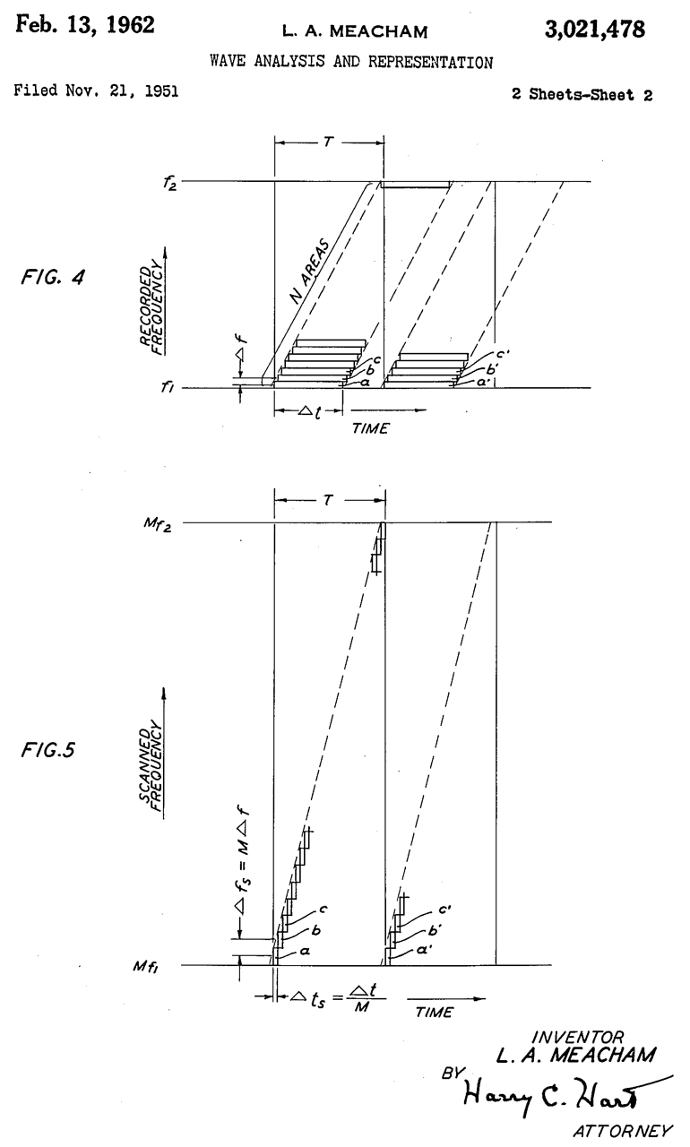
3021478 Wave analysis and representation, Larned A Meacham, Bell Labs, App: 1951-11-21, [Korean War] Pub: 1962-02-13, -
A suitable paper is the so-called Teledeltos facsimile paper of Western Union Telegraph Company.
"This invention relates to the analysis of signals into their several harmonic components and to the continuous display of the resulting spectrum for visual examination. Spectrum analyzers, or "spectrographs” as they have come to be termed fall into one or the other of two categories.
Those of the first category are distinguished by a large number of fixed filters, each of which is tuned to pass a narrow band of adjacent frequency components within the broader band of which the signal is composed. Such an instrument may be rapid in its action; indeed, it may perform its analysis continuously and substantially contemporaneously with the generation of the signal being analyzed, provided too high a degree of resolution is not asked of it. But the large number of fixed filters required makes it bulky and costly. Furthermore, unless the bands overlap sufficiently its operation when some component of the signal falls within a filter pass band differs from its operation when this component falls between adjacent bands.
An analyzer of the second category employs a heterodyne device, i.e., the combination of a single fixed filter, a Sweeping oscillator and a modulator, such that the modulation side frequencies pass through the filter in succession. Such an analyzer tends to be slower in operation than is one of the first category: for a resolution of the signal into N different frequency components the analysis, which with a spectrograph of the first category requires N fixed filters, requires only one filter in the second category, but also requires that this filter be used to examine the entire signal at each of N frequencies in succession. This demands recording and repeated scanning of the signal, and adequate time must be allowed for these processes."
[A third type not known then is a DSP approach like in the HP 4395A. This is much much faster and can provide true 1 Hz RBW.]
"It is the object of the present invention to reach a compromise between such apparently incompatible considerations, and to furnish a high resolution analysis of a signal on a continuous basis, and in some cases on a Substantially instantaneous or contemporaneous basis, ..."
3021479 Method and means for spectrum analysis of radio signals, Toro Michael J Di, Graham Walton, Navy, 1962-02-13, - "The usefulness of spectrum analyzers is evidenced by the large number which are commercially available. Some of the presently available instruments which work at sonic frequencies are the May Electric Sonolator and Sona-graph, the Panoramic Sonic Analyzer, the Western Electric 4-A Analyzer, the Hewlett-Packard Wave Analyzer and the General Radio Wave Analyzer. An important application of spectrum analyzers at the present time lies in the field of submarine and torpedo detection."
May Electric Sonolator
Kay Sona-graph, Jerry Proc,
Panoramic Sonic Analyzer
Western Electric 4-A Analyzer
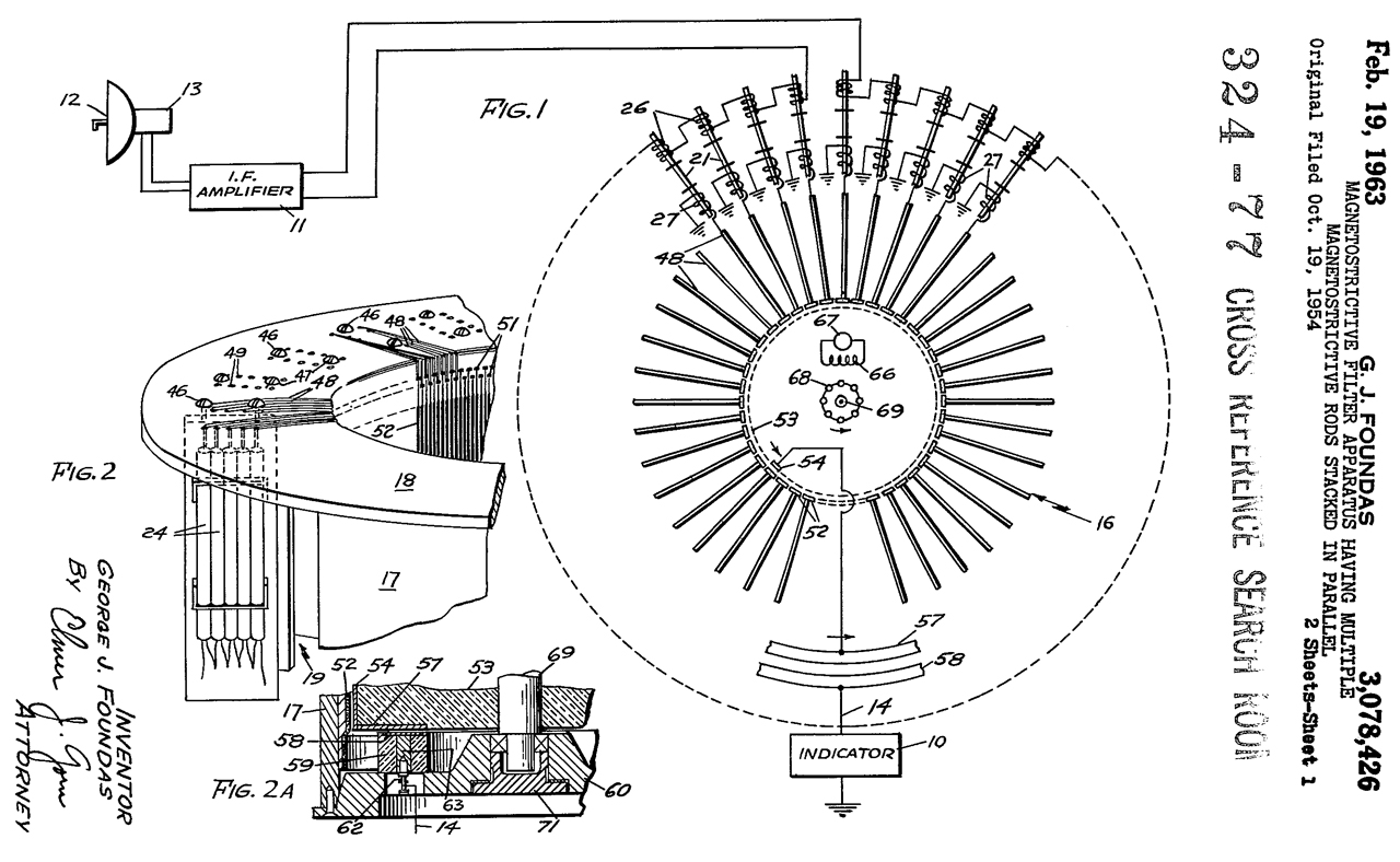
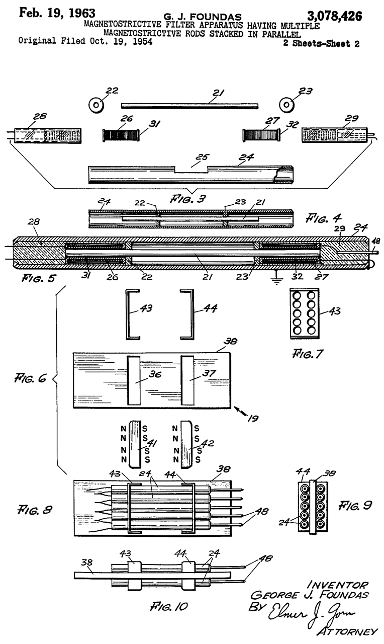
3078426 Magnetostrictive filter apparatus having multiple magnetostrictive rods stacked in parallel, George J Foundas, Raytheon, App: 1959-03-20, Pub: 1963-02-19, -
3096479 Energy spectrum and cross spectrum analysis system, Marks Wilbur, Paul E Strausser, Navy, 1963-07-02, -
This has a very strong feel of a DIFAR signal processor and maybe also LOFAR?
3217251 Orthogonal spectral analysis apparatus for message waveforms, Harold B Andrew, Bell Labs, 1965-11-09, - uses I&Q versions of the signal.
3249911 Method and device for determining the position of sound sources in water, Gustafsson Bengt Gunnar, US Philips Corp, 1966-05-03, - time delays on multiple channels - citations & cited by.
3344349 Apparatus for analyzing the spectra of complex waves, Manfred R Schroeder, Bell Labs, 1967-09-26, -
A delay line with multiple taps feeds I&Q detection. This is a huge improvement over prior art implementations.
3441850 Spectrum analysis apparatus, John F Frazer, Richard Holzman, Kenton J Ide, Richard K Moore, Signatection Inc, 1969-04-29, - similar to a drum FAX machine (WU FAX) Cites:
2403997 see above
2425003 see above
2532731 see above
3360724 see below (granted before 3441850 was granted)
3360724 Apparatus for analyzing electrical signals including magnetic storage means, Francis S Guros, James R Bradford, General Precision, 1967-12-26, - General Precision (Wiki) made military electronics.
3466540 nalysis of time-segmented waves, George H Robertson, Bell Labs, 1969-09-09, -
Talks about a number of the patents in this audio analysis section.
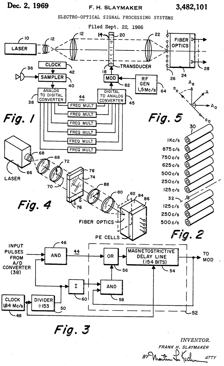
3482101 Electro-optical signal processing systems, Frank H Slaymaker, General Dynamics, 1969-12-02, -
The patent talks about speech, but I think GD is more into submarines.
3611411 Spectrum-analyzing recorder, Stephen L Moshier, Allan K Mccombs, Stanley R Rich, LISTENING Inc, 1971-10-05, - has chart recorder for permanent record.
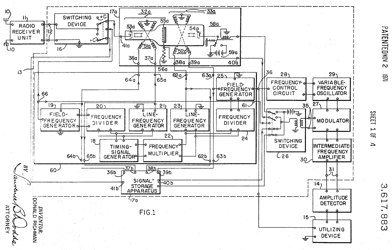
3617883 Spectrum-analyzing system, Donald Richman, Hazeltine, App: 1952-04-04 (TOP SECRET) Pub: 1971-11-02, - 500 Hz to 18,000 Hz - probably for a submarine
Cites 2403986 and 2425003
uses a pair of RCA Graphechon storage CRTs switched alternately.
RCA 1855 -
2815468 Graphechon storage tube (see above)
3656151 Digital function generation network, William E Richeson Jr, Mike B Feher (N4FS), Magnavox, 1972-04-11, 341/147; 341/153 -
"In the early days of DIFAR there was no real grayscale on the chart paper which indicated signal strength. Essentially you either had nothing or a real dark line. My logarithmic converter remedied that in that it allowed smooth transitions as signal strength varied. Of course now there would be so many better ways of doing it. However, at the time it worked and everyone was pleased. 73 – Mike"
PS Magnavox made the AN/GXC-7 Tactical Facsimile set for the Marines. "Any paper, using carbon paper transfer, including single copy sets, multiple copy sets, transparencies, map overlays, and view graphs"
NSN: 5815-01-067-4655
TM 11-5895-1079-14-1 (pdf)
TM 11-5895-1079-24P (pdf)
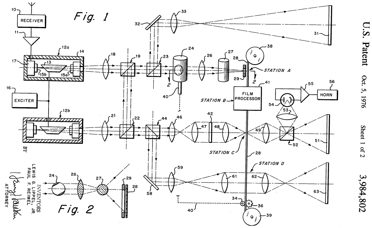
3984802 Feature recognition system, Lewis G. Lippel, Jr., Paul F. Reimel, Navy, App: 1966-06-27, SECRET, Pub: 1976-10-05, -
"It is generally known that each type or class of submarines, when submerged, generate a plurality of discrete underwater acoustical frequencies from propeller cavitation, inboard machinery, etc. The complex composite wave formed thereby is unique as a "signature' and can be used for recognition and identification. In ASW (antisubmarine warfare) it is desirable and often necessary to positively identify these signatures as opposed to those of other underwater sound sources when the submarine position has been localized and before executing appropriate action such as attack if the sound source were an enemy submarine. The most commonly known means for identifying acoustical signatures requires a frequency spectrum analysis. The acoustical signals detected by a sonobuoy are translated in an analyzer into a frequency spectrum and displayed on a recorder having a constant speed strip chart and a constant speed reciprocating and traversing pen. The line made by the pen is intensity modulated in accordance with the frequency predominance producing thereby a plurality of light and dark lines parallel to the length of the chart in coordinates of time vs. frequency. The AN/AQA-5 Sonobuoy Indicator Group, for example, produces such a display by taking 0.2 microsecond samples of the sonobuoy transmitted signal and integrating each frequency in the samples so that the line intensity produced by the pen varies with the frequency repetition rate. Noise frequencies appear as light lines because, their frequency repetition rates are practically zero, while a cavitating submarine generates discrete frequencies which occur in every sample and therefore appear as dark lines because of the high frequency repetition rate.
As applied to ASW and under average noise conditions, about three inches of recordation is deemed necessary for a skilled operator to positively recognize and identify an underwater object's acoustical signature. At conventional chart speeds of about 1 inch per minute, this imposes about three minutes of delay be tween when an object is first encountered and when a decision for appropriate action can be made. This delay may seriously derogate the effectiveness of ASW missions, particularly in this age of fast-moving submerged submarines.
The present invention contemplates an entirely new technique of feature recognition which automatically and instantaneously recognizes and positively identifies underwater object acoustical signatures by means of optical correlation of holograms."
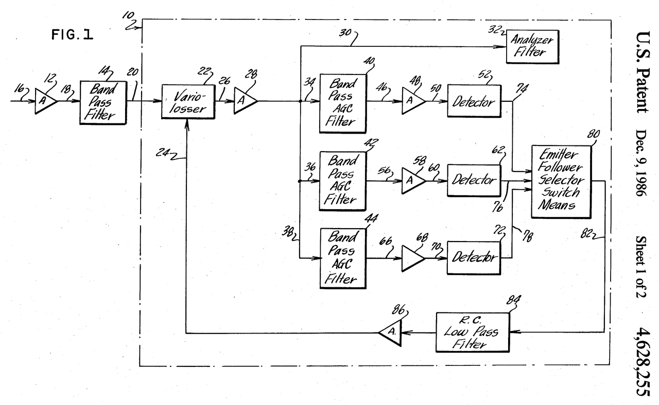
4628255 AGC technique for spectrum analyzers, William O. Dunnican, Navy, App: 1969-12-08, TOP SECRET, Pub: 1986-12-09, -
"When a spectrum analyzer output with widely varying spectral densities is presented on a limited dynamic display medium, an automatic gain control is needed. Traditionally, LOFAR analysis has been displayed on "Timefax' electrosensitive paper which has a very limited range of approximately 6 db.
Since a LOFAR spectrum may have a range of 40 db across the frequency band of interest, a stiff AGC is required to maintain the output within the 6 db range of the display medium. In a typical LOFAR spectrum analyzer with AGC, the AGC filter bandwidth is about 50 times the analyzing bandwidth, that is 10 Hz vs 0.2 Hz, and the AGC stiffness is about 1 db change of the output for a 15 db change of the input. Now, a strong signal within the AGC filter bandwidth causes a decrease in gain throughout the AGC filter bandwidth and hence a "whitening' of the recorded spectrum response on the electrosensitive paper about the strong signal to the width of the AGC filter. If weak signals are present at frequencies falling in the area of whitening, they will not be displayed. One prior art approach to overcoming the problem of whitening is found in U.S. Pat. No. 2996667 issued to R. R. Galbreath."
Sounds like AQA-5.


Side Scan Sonar
Placed here in the hope it will lead to patents on processing DIFAR signals.
4197591 Facsimile recording of sonic values of the ocean bottom, Julius Hagemann, App: 1958-08-04, TOP SECRET, Pub: 1980-04-08, - Side Scan Sonar (Wiki)
Calls: (Bold Red = Top Secret)
1625245 Receiving system for compressional waves
John Hays Hammond Jr 1918-06-22
1927-04-19
1973719 Apparatus for and method of locating sunken vessels and other objects
Lake Simon 1932-01-07 1934-09-18
2167492 Method of echo sounding and means therefor
Hughes Henry & Son Ltd 1935-01-14 1939-07-25
2403562 Recorder for radar systems
RCA corp
1943-08-30 1946-07-09
2418846 Submarine detection system
(PPI, enabling for SOSUS?)
Larned A Meacham Bell Labs
1943-12-03 1947-04-15
2433971 Underwater image transmitting apparatus
Arthur R Cassidy 1944-02-28 1948-01-06
2476032 Doppler effect speed and drift indicating system
Bell Labs 1944-03-08 1949-07-12
2528119 Frequency modulation range finder
RCA corp 1947-04-25 1950-10-31
2648838 Indicating and recording systems
Haller Raymond And Brown Inc 1949-07-27 1953-08-11
2729803 Recording depth sounder
Raytheon 1949-12-22 1956-01-03
2729910 Controllable depth maintaining devices
Raytheon 1950-04-26 1956-01-10
2751703 Fishnet adjustable in depth
Atlas Werke Ag 1952-03-17 1956-06-26
2821805 Fish finding apparatus
Raytheon 1954-04-14 1958-02-04
2825884 Echo ranging devices
Raytheon 1953-05-14 1958-03-04
2838850 Virtual target for echo ranging apparatus
Edward B Stephenson 1943-09-15 1958-06-17
2853824 Submarine echo-sounding apparatus for fishing vessels
Pye Marine Ltd 1954-09-27 1958-09-30
2919423 Submarine bottom scanner
William H Williams 1954-04-29 1959-12-29
2997689 Distance measuring apparatus (non magnetic transducers)
Ford L Johnson 1946-03-26 1961-08-22
3005973 Submarine locating system (port & Starboard search pattern)
Atlas Werke Ag 1954-02-13 1961-10-24
3021807 Homing system for torpedo
ecil K Stedman 1946-05-01 1962-02-20
Photos
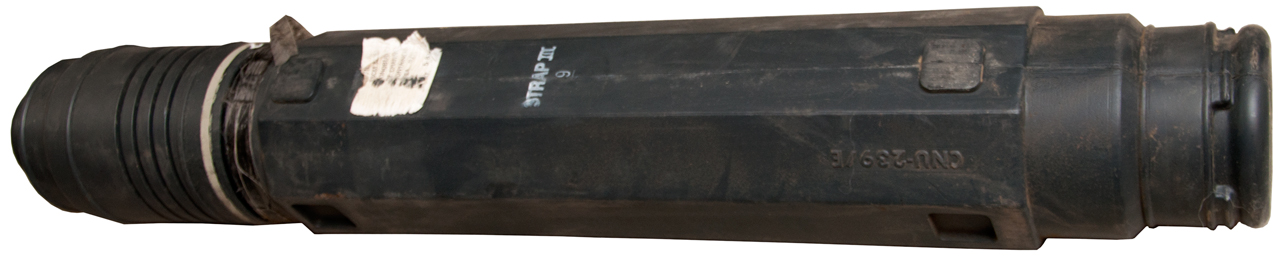
Fig 1 CNU-239/E Shipping Tube
Fig 2 Sonobuoy in launch tube beside shipping tube.
Patents
SSQ-53 Related
3006002 Air-sea-rescue drift buoy, Frederick De W Pingree, Robert G Walden, Harold E Sawyer, Navy, 1961-10-31, -
(1) Dimensions identical with those of Sonobuoy AN/SSG-2,
(2) Incorporate a UHF transmitter designed to operate on 243 megacycles and to be received and homed on by such airborne equipment as AN/ARC-27 andvAN/ARA-25; and
(3) Have maximum signal range, with operating life a lesser consideration.
3047259 Speed brake retarding mechanism for an air-dropped store, George J Tatnall, Albert F Scarcelli, Navy, 1962-07-31, - makes use of mouse trap wire mechanisms
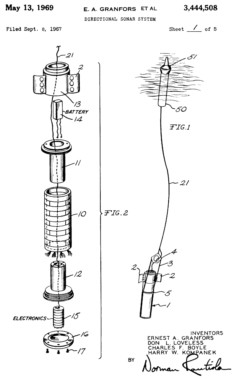
3444508 Directional sonar system, Ernest A Granfors, Don L Loveless, Charles F Boyle, Harry W Kompanek, , Sparton Corp.,1969-05-13, 367/3; 367/99; 367/126 - UHF command activated (by only pinging on demand battery life is saved), active sonar, fluxgate compass. This is NOT the SSQ-53, but has some commonality. Piezo elements an array to both have a beam direction and other for an omni-directional pattern.
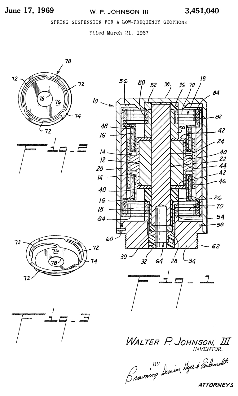
3451040 Spring suspension for a low-frequency geophone, Walter P Johnson, Shawcor Ltd, App: 1967-03-21, Vietnam, Pub: 1969-06-17, - Spring design allows small diameter and lower frequency operation in oil exploration.
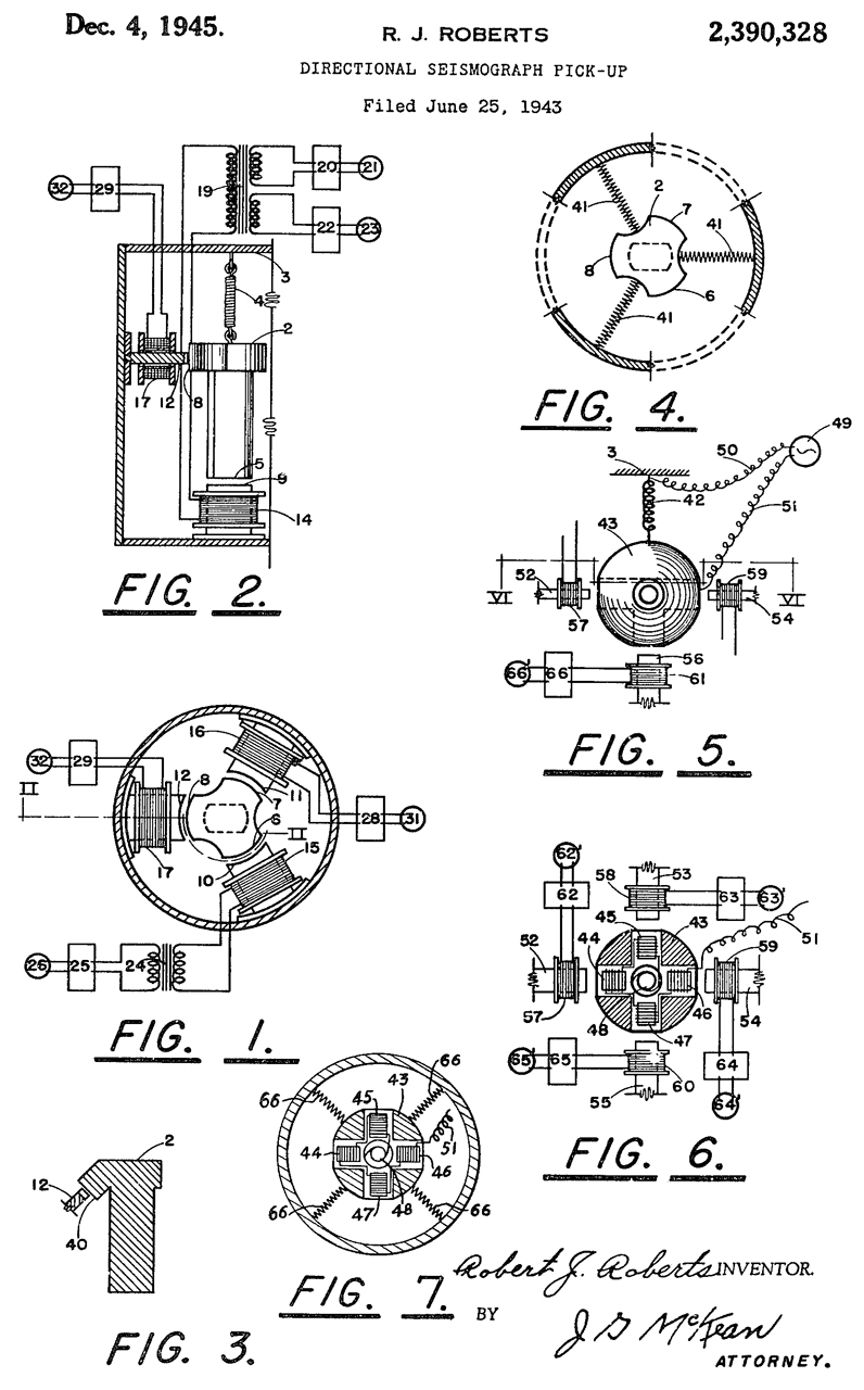
2390328 Directional seismograph pickup, Robert J Roberts, Standard Oil Development, 1945-12-04, -
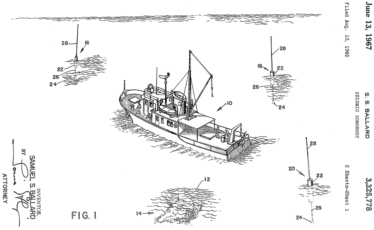
3325778 Seismic sonobuoy, Samuel S Ballard, Lockheed, 1967-06-13, -
oil exploration
3660807 Towed body vertical attitude stabilization system, Donald R Depew, Karl L Greenman, Daniel C Probert, Sparton Corp.,1972-05-02, -
probably not the SSQ-53, but looks like the vane and parachute support ring on the SSQ-53.
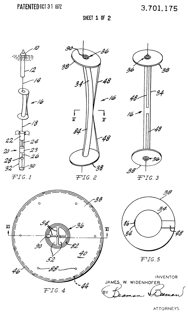
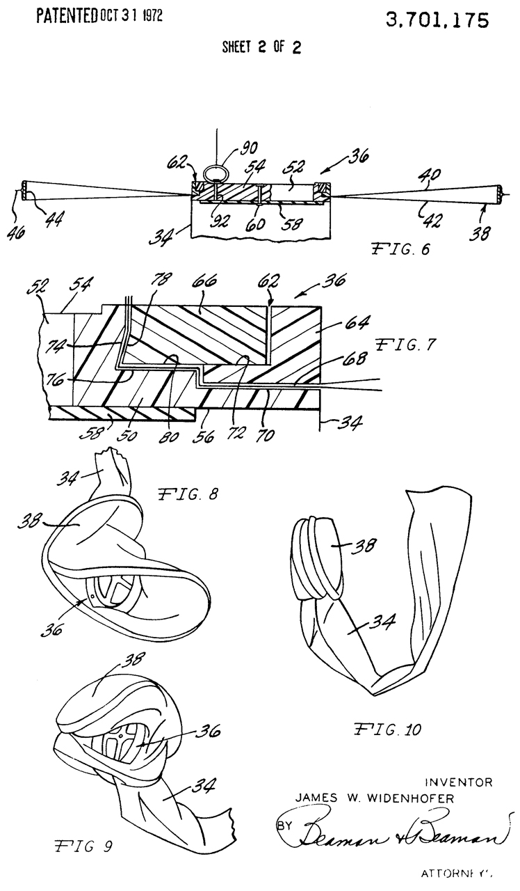
3701175 Hydrophone damper assembly, James W Widenhofer, Sparton Corp.,1972-10-31, 441/22; 114/243; 174/42; 367/3; 367/157; 367/173 -
RE28671 Hydrophone damper assembly, James W Widenhofer, Sparton Corp., 1976-01-06, 441/22; 367/173 - "... to reduce extraneous noises and signals and permit the most accurate sound pressure wave input characteristics."
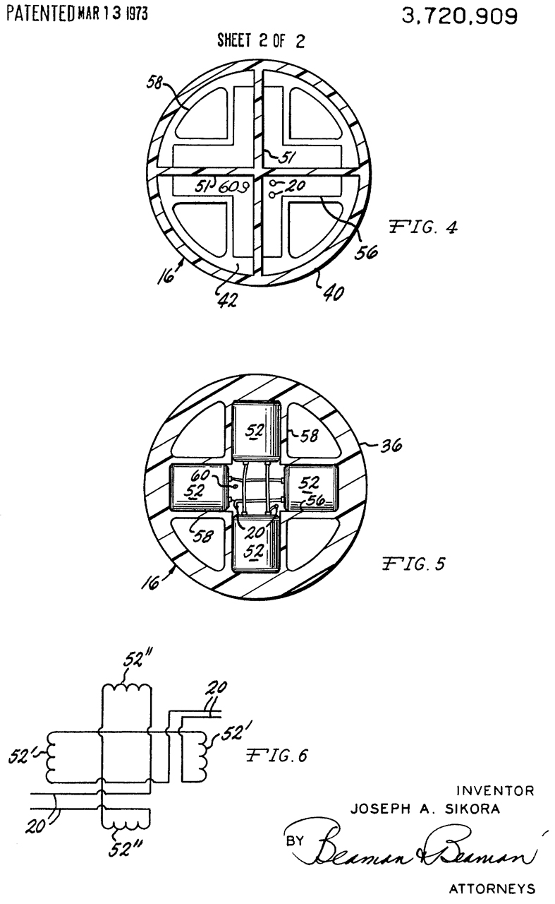
3720909 Directional hydrophone buoy system, J Sikora, Sparton Corp., 1973-03-13, 367/173 -
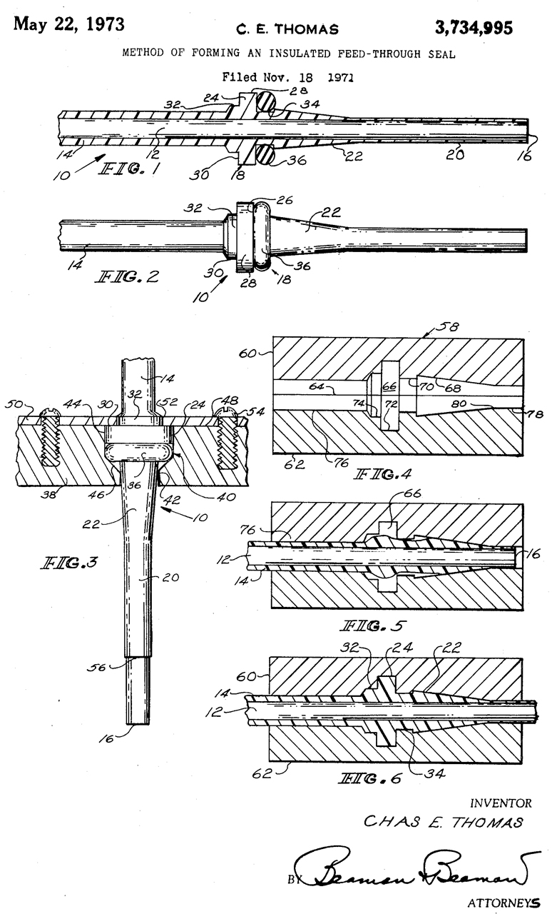
3734995 Method of forming an insulated feed-through seal, C Thomas, Sparton Corp, 1973-05-22, - to seal joint between cable that's in ocean and dry electronics compartment.
3786403 Underwater acoustical detection system, A Will, S Wolf, W Barnum, Navy, App: 1968-05-10, SECRET, Pub: 1974-01-15, - Search-In-Depth Concept of Acoustic Ranging (SIDECAR) has been formulated to exploit the phenomena of deep-water convergence zones.
3921120 Float Actuated Release Mechanism, James W Widenhofer, Sparton Corp., Nov 18 1975, 367/4; 116/209; 441/33 -
3953829 Partially filled fluid damped geophone, Charles F. Boyle, Sparton Corp,1976-04-27, -
3980985 Suspension system for directional hydrophones, John R. Dale, William F. Brenner, James F. McEachern, Walter L. Leupold, Edward A. McDemus, Navy, 1976-09-14, -
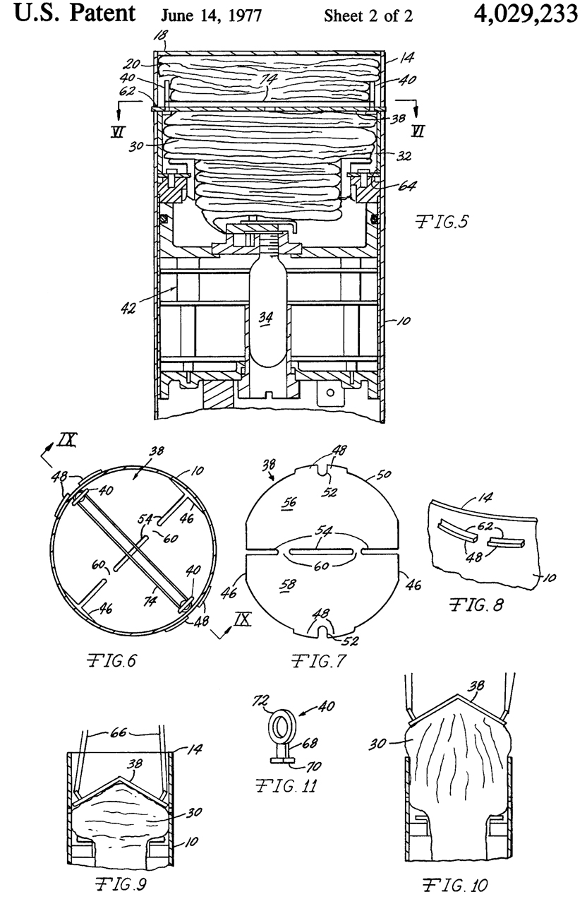
4029233 Sonobuoy retainer plate, James W. Widenhofer, Sparton Corp.,1977-06-14, 220/89.2; 137/67 -
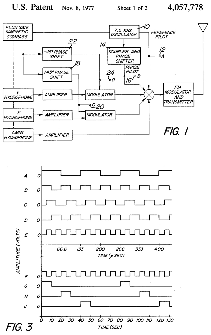
4057778 Built-in test equipment for sonobuoy, Albert M. Bates, Anthony J. Madera, Navy, 1977-11-08, -
Fig 1: Block diagram of DIFAR sonobuoy
Fig 2: Block diagram of Built-In-Test circuits - for which models/versions?
Fig 3: Timing diagram
Powered by its own sea water activated battery, Fig 2 (26), that only lasts for a couple of minutes.
So the BIT functions just after the sonobuoy hits the water and stops when the testing is complete. The patent mentions disabling the buoy if it fails BIT, but it may transmit a pass or fail tone sequence at the end of the BIT, Fig 2 (88).
4096598 Selected depth mooring system, Russell I. Mason, 1978-06-27, -
This may or may not apply to sonobuoys.
4195359 Automatic echo detection and classification system, Paul H. Miller, Tillman H. Schafer, App: 1954-06-28, TOP SECRET, Pub: 1980-03-25, - Automatic Detection And Classification (ADAC)
4262069 Lead chloride battery plate, John L. Devitt, Douglas E. Johnson, Robert S. Willard, Sparton Corp, 1981-04-14, - "A seawater activated battery plate"
4494024 One shot spring activated motor, Gerald W. Braun, Magnavox, 1985-01-15, - blowing a resistor causes a shaft to turn either CW or CCW. For use in a sonobuoy.
4590590 Sonobuoy multiple depth deployment apparatus, James R. Toone, Robert L. Barker, Magnavox,1986-05-20, -
4628255 AGC technique for spectrum analyzers, William O. Dunnican, Navy, App: 1969-12-08, TOP SECRET, Pub: 1986-12-09, - see 4628255
4654832 Sonobuoy retaining and release apparatus, Robert L. Barker, Magnavox,1987-03-31, -
"In one previous system, the shroud line end ejection and float exit are effected by a bendable retaining plate releasably mounted near the casing one end. An inflatable float bag of a flexible material such as a heavy plastic is positioned inside the casing and after the sono buoy is in the water the bag is inflated as from a pressurized canister. When the bag pressure is sufficiently high, a bending force is applied to the plate causing it to buckle and be ejected from the outer casing, whereupon the shroud line ends are ejected and the bag exits the casing and rises to the water surface. This system is relatively expensive owing to the cost of the inflatable bag and pressurized cartridge, has a relatively low shelf life due to gradual pressure loss from the cartridge, and requires differently sized and/or configured plates and cartridges for different size buoys." sounds like the prior art description matches the SSQ-53. See 4029233 & 3921120
The float is a rigid cylindrical canister - no CO2 cartridge - longer shelf life
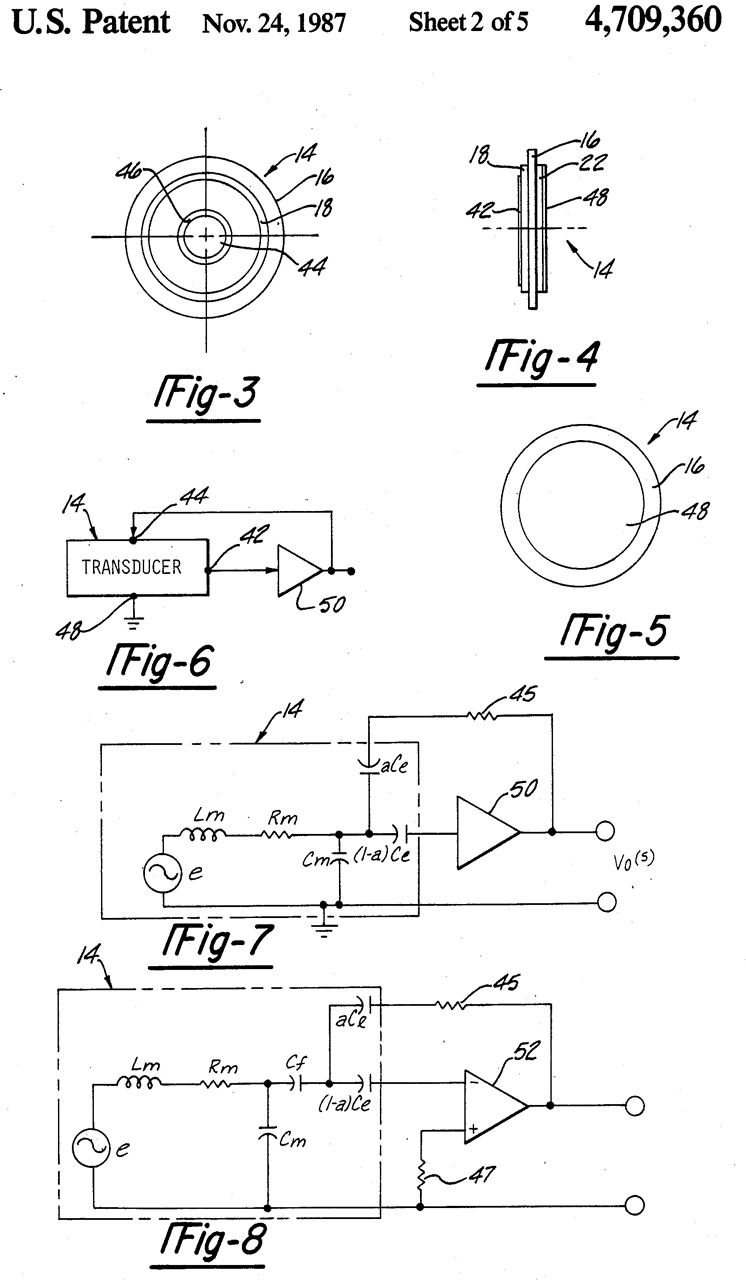
4709360 Hydrophone transducer with negative feedback system, Robert J. Martin, Claude Sims, Sparton Corp., 1987-11-24, - broader frequency response, not SSQ-53.
may have general use for small speakers.
4738421 Self-orienting device, Richard F. Green, LeRoy L. Manor, Sparton Corp.,1988-04-19, - for a Sonobuoy, but is it for SSQ-53?
5084846 Deep submergence hydrophone, Daniel P. Smith, Jr., Sparton Corp.,1992-01-28, - This is the same geophone technology as in patent 3720909 except made to work much deeper.
5379267 Buoyancy control system, David C. Sparks, Luke Belfie, Dave Bruder, Christian T. Werner, James W. Widenhofer, Sparton Corp, 1995-01-03, - to keep sonobuoy at fixed depth. an early system that uses 2 liquids, one denser than sea water, and one lighter.
It's my understanding that modern buoys can change their density (ncbi). This is an extremely difficult thing to do.
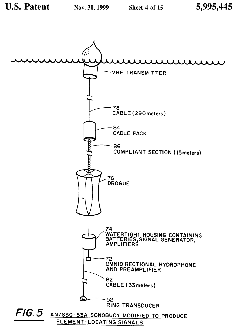
5995445 Acoustic survey technique, Eric James Whitesell, Darrell E. Marsh, Shelby F. Sullivan, Navy, App: 1980-04-18, TOP SECRET, Pub: 1999-11-30, -
"The system 20 is designed to be deployed by a P-3C antisubmarine patrol aircraft and to make use of the aircraft's AN/ARR-72 radio telemetry receiver 32, and AN/AQA-7 narrowband analyzer and display 34. The receiver 32 is manufactured by General Dynamics Electronics, of San Diego, Calif., whereas the analyzer 34 is manufactured by the Magnavox Corp."
"The random Sonobuoy array 40, shown in FIG. 3, is formed with thirty-one modified AN/SSO-53A Sonobuoys 42 distributed over circular area 44 on the surface of the ocean. Each Sonobuoy 42 deploys a passive wide-band hydrophone 46 at a depth of 305 meters (1,000 feet), resulting in a two-dimensional, disk-shaped array 48 of thirty-one receiving element 46.
Four of the Sonobuoys 42 also deploy a low-power active acoustic Source 52 which continuously transmits high frequency band-limited, pseudorandom, noise at an individual center frequency of f=10.5, 13.0, 15.5, and 18.0 kHz, with a bandwidth W=1,000 Hz. The active sources 52 are suspended below the hydrophones 46 and their respective sonobuoys 42 by a cable 54 of known length. The high frequency signals are used by the locating System 24, FIG. 2, to determine the relative position of each of the thirty one receiving elements, 46 of FIG. 3."
"Reference is now directed to FIG. 5. The AN/SSO-53A Sonobuoy 70 was chosen for the array of this invention for three reasons. First, it had a sensor 72 deployable to a depth of 305 meters (1,000 feet) assuring good acoustic coupling with long-range Signal propagation paths. Second, it provided water tight housing 74, also deployable to 305 meters, with sufficient room to hold the batteries and circuitry associated with the four active sources, 52 of FIG. 3. Finally, it deployed a large drogue 76, FIG. 5, just above the hydrophone 72. This drogue 76 was designed to isolate the hydrophone 72 from cable 78 strumming and to decouple it from noise-inducing surface wave motion. It is believed that the drogue 76 also tends to couple the sonobuoy 70 hydrodynamically to the slower, more uniform, deep ocean currents and to prolong the life of the array by slowing the rate of sonobuoy dispersion (refer back to FIG. 4).
Two modifications of the Sonobuoy 70, FIG. 5, were required to adapt it to the requirements of this invention. The first was replacement of the normal DIFAR hydrophone with a calibrated omnidirectional hydrophone with a relatively flat response up to 20 kHz. The extended receiving band allows detection of the high-frequency signal generated by the active Sources within the array, while the use of a calibrated hydrophone 72 reduces signal loss during beam forming. The hydrophone 72 selected was that normally used on the AN/SSO-57A Sonobuoy.
Reference is now directed back to FIG. 3. The second modification to the Sonobuoy which was required was the addition of the active Source and associated circuitry 52 to four of the thirty one sonobuoys 42. The source 52, shown as a ring transducer 52 in FIG. 5, is a free-flooding cylindrical ring three inches in diameter and 1-1/2 inches long, Suspended by a cable 82 approximately thirty-three meters below the passive hydrophone 72. This separation was required by the locating System, 24 in FIG. 2, to provide a Vertical measurement base line for determining the depth of hydrophones 72, FIG. 5. It also helped to reduce the dynamic range requirement of the receiving electronics. The dynamic range requirement was further reduced by the use of the ring transducer 52, which produces a dipole radiation pattern with a fifteen-dB null steer toward the hydrophone 72."
6130857 Aural enhancement of active sonar systems, Jack R. Williams, Shelby F. Sullivan, James M. Alsup, Navy, App: 1985-03-15, TOP SECRET, Pub: 2000-10-10, -
"Further, the transmit frequency of active sonar systems has been lowered in order to achieve longer ranges within the ocean medium. Typical operational frequencies have been changed from 26-38 kHz for the older systems to 6.5-9.5 kHz for more modern systems. This is a decrease by a factor of four and has effected the resultant hearable frequency offset caused by Doppler shift which had been monitored aurally by the operator. The decrease in Doppler sensitivity is particularly noticeable for shallow-water and/ or low-velocity target conditions for which reverberation can more easily mask target echoes. These are generally thought to be the primary reasons for the decreased use of the audio capability or channel for active target detection.
This invention addresses the general problem of converting received Sonar signal data for modern high frequency Sonar systems into signals which can be monitored in the audio frequency range by a human operator. More particularly, a method and device is presented which accepts as input the “normal” audio signal provided by an existing Sonar processor, e.g., the Navy's AQA-7 receiver, and provides as output an enhanced audio signal more suitable for the recognition and detection of Sonar target echoes, specifically in the low-doppler region."
7986585 Reception of uplink data from sonobuoys, Donato M. Russo, Ronald Buratti, Navy, 2010-05-06, -
Presently a large number of ASW aircraft use sonobuoy receivers that have been in service for a number of years, for example, the AN/ARR-78 and modifications, as well as the ARR-78, ARR-84, ARR-78 v3. ARR-89, and modifications of those units (collectively referred to herein as “legacy Sonobuoy receivers.) The legacy Sonobuoy receivers contain twenty or four receiver modules, depending on the model, each capable of accepting operating channels 1-99 (those Sonobuoy channels now in use and those being developed for future use) in the VHF band from 136 to 173.5 megahertz (MHz). The receiver modules may be tuned to any one of the Sonobuoy operating channels. The output from the legacy sonobuoy receivers is fed to a data demultiplexer which is implemented on a personal computer referred to as a Low Cost Advanced Processor (LCAP) and which transforms the receiver frequency shift keyed (FSK) output to a digital stream that can be processed with a conventional computer. The LCAP output is passed to an AN/UYS-1 or AN/UYS-1A single advanced signal processor (SASP) system. The SASP system includes a spectrum analyzer and programmable sig nal processor that extracts and conditions acoustic Sonobuoy data to determine frequency, amplitude, bearing, Doppler, range, and other characteristics for detection and tracking of underwater targets.
While the legacy sonobuoy receivers are highly reliable, they have certain inherent limitations that restrict the insertion of new technology. In particular, reception of FSK modulated digital transmissions from recently developed sonobuoys, for example, the AN/SSO-101 and AN/SSO-110 (referred to herein as “digital sonobuoys'), have presented new challenges. Although the legacy Sonobuoy receivers are able to demodulate signals from the digital Sonobuoys and can do so at the highest data rate of 256 kbps, they cannot perform any operations to reduce the bit error rate (BER). Systems that use digital sonobuoys require a BER of 10 (1 error in 100 Kbits), or better.DIFAR
DIrectional Frequency Analysis & Recording is a way to get a magnetic bearing to go with the SIN and COS audio signals. When working on this web page I realized that I have not seen any mention of the sonobuoy operators equipment. Some of the below patents hint that there's a CRT display similar to a RADAR PPI display. If you know with a DIFAR display looks like or its nomenclature please let me know.
2629083 Expendable radiosonic buoy, Russell I Mason, Joseph A Barkson, James C Mcnary, Navy, App: 1944-09-21, Pub: 1953-02-17, - This is the CRT-1 Sonobuoy which has an omnidirectional pattern. So the next generation would be a directional pattern.
2634316 Control compass with universal drive, George E Breeze, Navy, App: 1946-07-23, Pub: 1953-04-07, -
A compass specifically for use in a sonobuoy. Probably the CRT-4.
2641751 Hydrophone casing, Russell I Mason, John F Ripken, Jr Hector F Bernier, Navy, App: 1944-05-11, Pub: 1953-06-09, - looks like the one used on the CRT-1.
2644243 Control compass, George E Breeze, Russell I Mason, Navy, App: 1944-11-20, Pub: 1953-07-07, -
2828475 Remote control or measurement indicating means, Russell I Mason, Navy, App: 1944-03-16, Pub: 1958-03-25, -
Sonobuoy (25) is slowly rotated [maybe by a jet of water (46)]. Floating magnetic element (40) causes the capacitance of a "control compass" to change which in turn changes the center RF frequency of an FM transmitter. The Automatic Frequency Control circuit of the receiver (15) tracks the transmit carrier frequency and that's read out on a voltmeter (20) which can be calibrated in compass bearing.
2938483 Acoustic decoy, Russell I Mason, Navy, App: 1945-11-29, TOP SECRET for 15 years, Pub: 1960-05-31, 114/20.1; 369/69; 367/1 -
A torpedo like device where a phonograph player, amplifier and speaker put sound in the water.
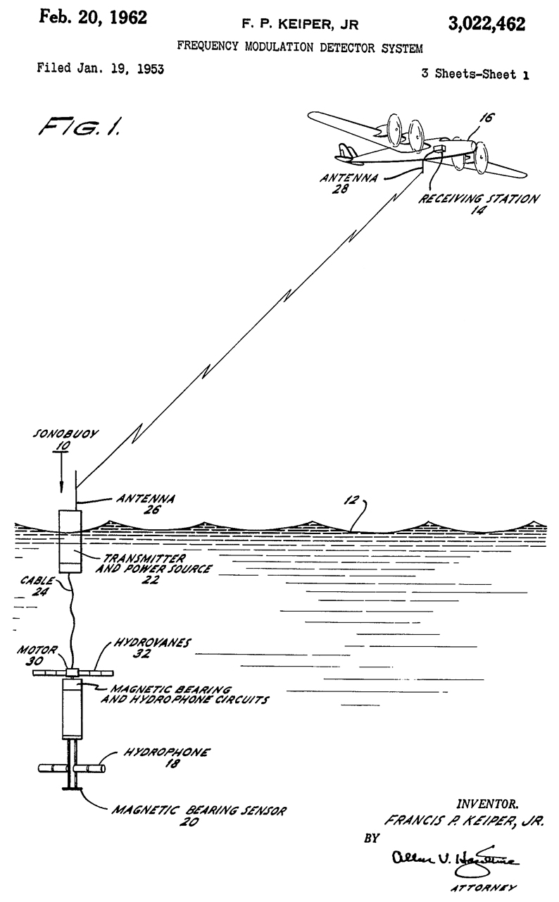
3022462 Frequency modulation detector system, Jr Francis P Keiper, Space Systems Loral, App: 1953-01-19, Pub: 1962-02-20, - Probably for the SSQ-2 (see AQA-1) which had a directional hydrophone which rotated slowly (3 RPM). A compass needle (bar magnet) rotates inside four saturable reactors whose inductance changes giving SIN and COS signals for the magnetic direction of the beam.
Rotating Directional Receiving Hydrophone
More on the SSQ-2 at jproc.
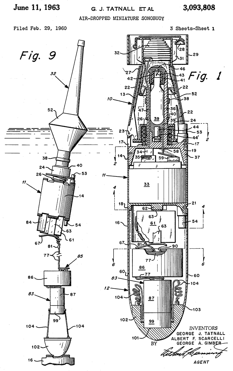
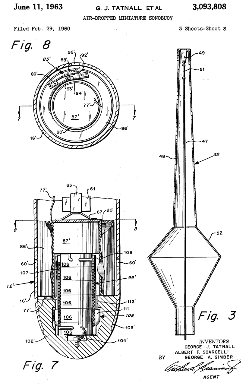
3093808 Air-dropped miniature sonobuoy, George J Tatnall, Albert F Scarcelli, George A Gimber, Navy, 1963-06-11, - Prior art sonobuoys were 3' long, 5" diameter and weighed 16 to 20 pounds limiting aircraft time on station and had a max depth of about 50'. This one is 15" long, about 3" dia and weighs about 5 pounds with a max depth of 300'.
The antenna on this looks like the antenna on 3290642.
3148351 Directional hydrophone system, Bartlett Lab, 1964-09-08. - The SIN and COS outputs of a cylindrical hydrophone (10) and combined with the output of a pair of Hall magnetic sensors (46 & 47) using balanced modulators to get the DIFAR signal.
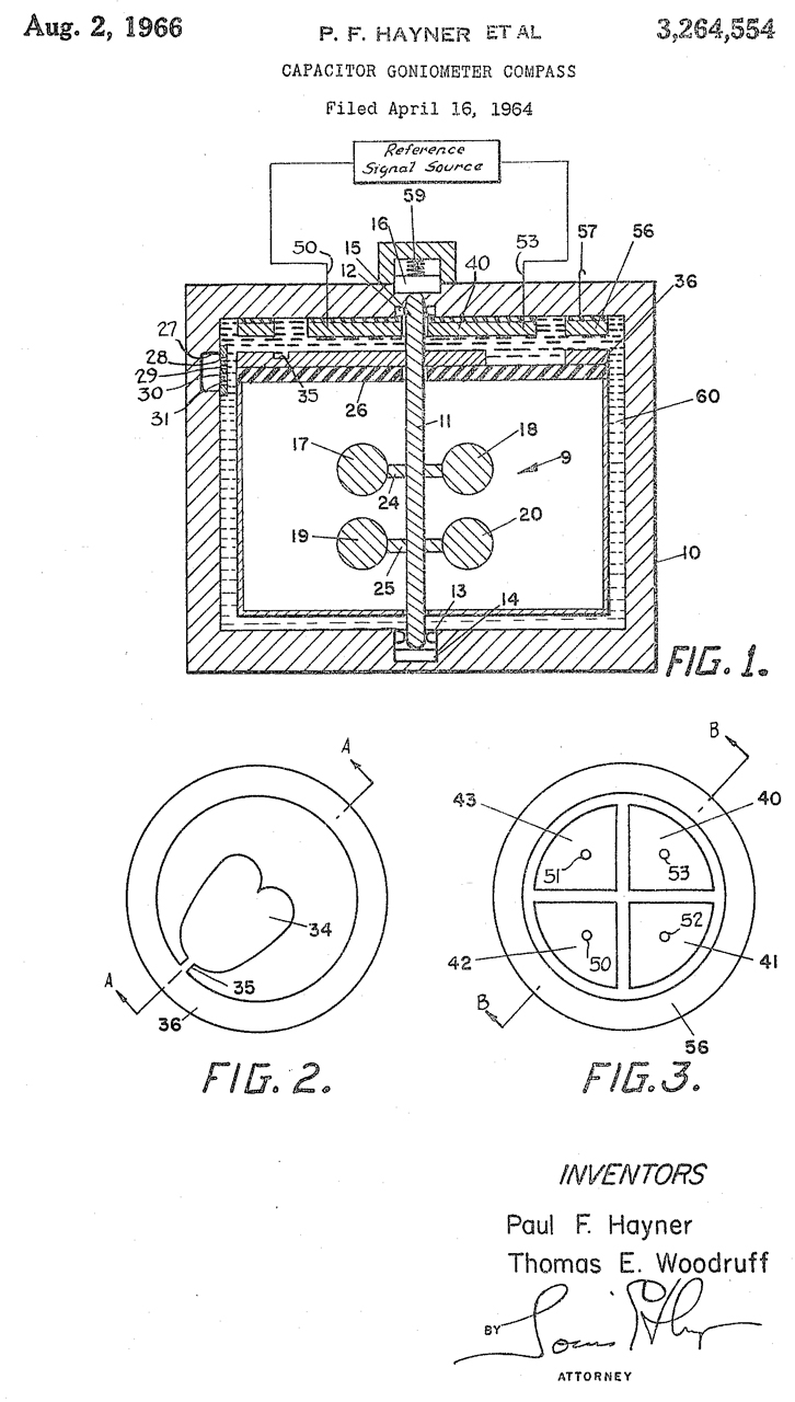
3264554 Capacitor goniometer compass, Paul F Hayner, Thomas E Woodruff, Lockheed/Sanders, 1966-08-02, -
A goniometer driven by a compass specifically to generate DIFAR signals.
3286224 Acoustic direction finding system, Arthur H Zefting, General Dynamics, 1966-11-15
3290642 Directional sonobuoy, Russell I Mason, Francis E Buck, Navy, 1966-12-06, -
Mechanically Rotating Directional Receiving Hydrophone
CRT-4 or SSQ-1?
Note this needs a magnetic bearing signal to go along with the audio so you know where the beam is pointing.
3369235 Directionally selective energy receiving system, Charles E Odams, Morton F Spears, Gorham Corp, 1968-02-13, - written for a loop and whip antenna using vacuum tubes, but may be the heart of DIFAR.
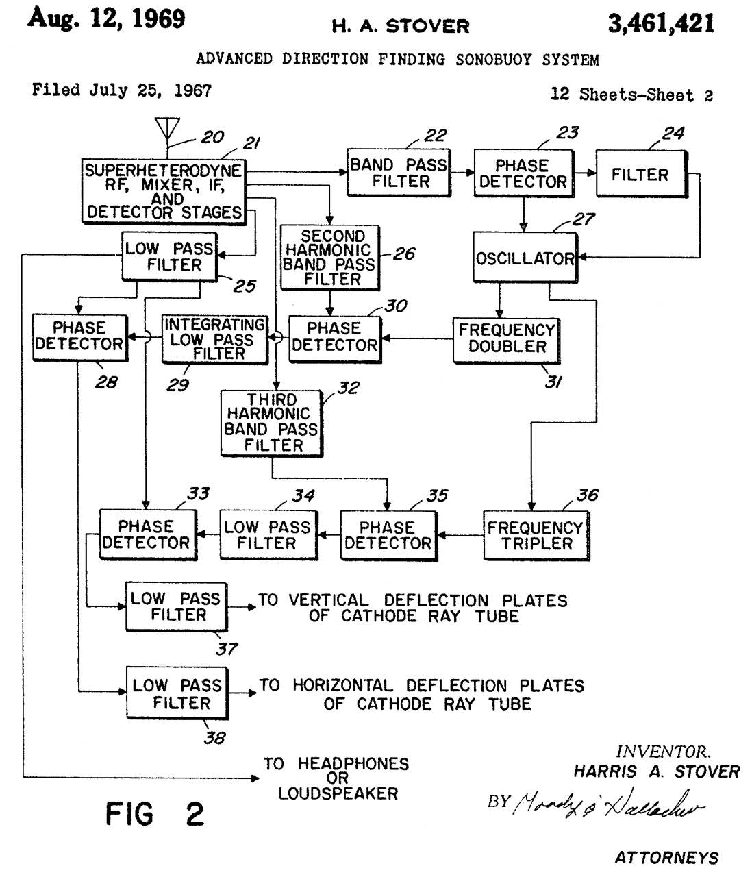
3461421 Advanced direction finding sonobuoy system, Harris A Stover, Collins Radio, 1969-08-12, -
Output to vertical and horizontal deflection plates of CRT.
3656151 Digital function generation network, William E Richeson Jr, Mike B Feher (N4FS), Magnavox, 1972-04-11, 341/147; 341/153 -
"In the early days of DIFAR there was no real grayscale on the chart paper which indicated signal strength. Essentially you either had nothing or a real dark line. My logarithmic converter remedied that in that it allowed smooth transitions as signal strength varied. Of course now there would be so many better ways of doing it. However, at the time it worked and everyone was pleased. 73 – Mike"
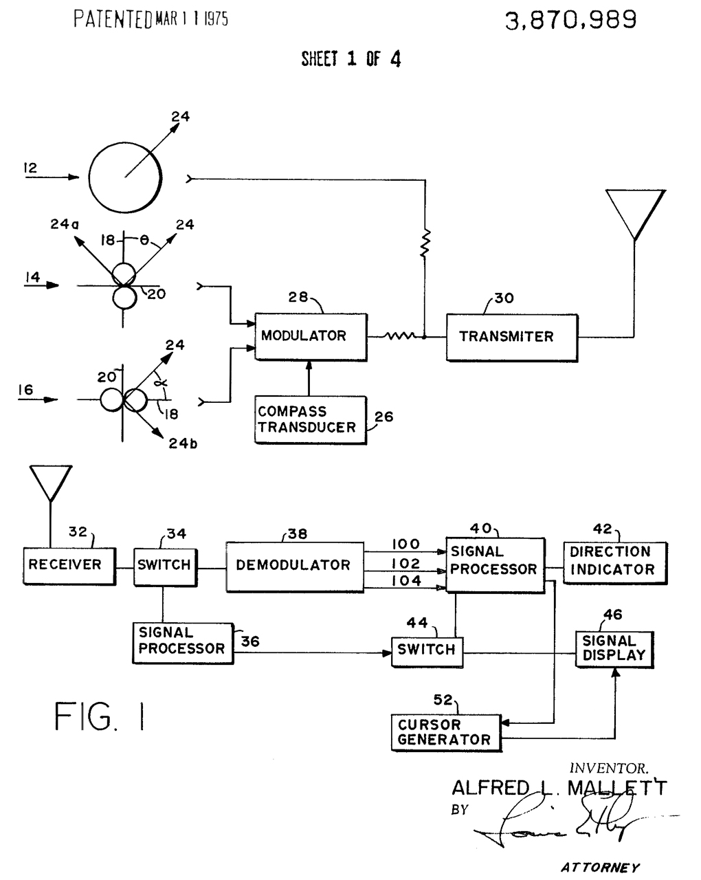
3870989 Underwater direction signal processing system, Alfred L Mallet, Lockheed/Sanders, 1975-03-11, -
Receiver has cursor generator and direction indicator
4078222 Direction determining apparatus, Thomas E. Woodruff, Navy, 1978-03-07, - DIFAR has bearing indicator as output, so only works on the loudest sound heard
4096598 Selected depth mooring system, Russell I. Mason, 1978-06-27, -
4205396 Automatic DIFAR cardioid former, Cabell N Pryor Jr, Navy, App: 1975-03-25, Pub: 1980-05-27, -
4868792 DIFAR demultiplexer test circuit, Gilbert R. Grado, Boeing, 1989-09-19, -
4879694 DIFAR demultiplexer circuit, Gilbert R. Grado, Boeing,1989-11-07, -
Magnavox & Bell Labs
2913073 Extensible antenna, Wendling John, Magnavox, 1959-11-17, - for ocean marker buoy (not sonobuoy)
2976408
3277404 Ultrasonic delay device, Everett L Fabian, Bell Labs, 1966-10-04, - ultrasonic delay line
3291092 Mooring apparatus, Paul V Halberg, Clinton S Myers, Magnavox,1966-12-13, - for buoy or mine?
3449711 Beam former, Luther W Ricketts Jr, Robert E Stalcup, Robert J Erickson, Magnavox,1969-06-10, - SOSUS?
3471838 Simultaneous read and write memory configuration, Luther W Ricketts Jr, George L Buenger, Robert J Erickson, App: 1965-06-21, Pub: 1969-10-07, - SOSUS?
3517399 Mooring apparatus having a free floating buoyant element, Maurice Horowitz, Clinton S Myers, Magnavox,
3532867 Delay correlator, Luther W Ricketts Jr, Robert E Stalcup, Robert J Erickson, George L Buenger, Everett L Fabian, Magnavox, App: 1966-04-04, Pub: 1970-10-06, - SOSUS?
3541451 Variable center frequency filter for frequency modulation receiver, Laurel R Lind, Magnavox,1970-11-17, - 10.7 MHz + or - 0.1MHz linked to AFC - sounds like DIFAR Rx
3584243 Acoustic transducer, Everett L Fabian, Acoustic transducer, Everett L Fabian, Magnavox,1971-06-08, - piezo hydrophone N-S shear at one end and E-W shear at the other end - sounds like a DIFAR hydrophone, 20 Hz to 5 kHz,
3603921 Sound transducer, Robert H Dreisbach, Magnavox, App: 1968-12-18, TOP SECRET, Pub: 1988-09-07, - piezo vane hydrophone for DIFAR
3656151 Digital function generation network, William E Richeson Jr, Mike B Feher (N4FS), Magnavox, 1972-04-11, 341/147; 341/153 -
"In the early days of DIFAR there was no real grayscale on the chart paper which indicated signal strength. Essentially you either had nothing or a real dark line. My logarithmic converter remedied that in that it allowed smooth transitions as signal strength varied. Of course now there would be so many better ways of doing it. However, at the time it worked and everyone was pleased. 73 – Mike" See AQA-7.


Autolycus
- Sniffer
The submarine detector (Wiki) - "Autolycus was an ion-mobility spectrometer (IMS). ". works by smelling the diesel exhaust. The US AN/ASR-3 (Sonobuoy Ref 19) Sniffer was fitted on a number of aircraft types.
2331190 Mass spectrometer, Jr John A Hipple, Westinghouse, App: 1940-08-02, Pub: 1943-10-05, 250/295; 250/427; 313/230; 313/323; 313/361.1; 338/116; 338/190 -
2354122 Vacuum tube, Jr John A Hipple, Westinghouse, App: 1942-04-17, Pub: 1944-07-18, 313/313; 313/326 -
2355658 Method and apparatus for mass spectrometry, Reed C Lawlor, App: 1940-04-17, Pub: 1944-08-15, 250/283 313/552 327/510 250/299 - oldest patent in class 250/283.
Class 250: Radiant Energy, (281) IONIC SEPARATION OR ANALYSIS, (283) With collection of ions - Wiki: Mass spectrometry
---------------------- Sniffer ---------------------
GB554792 An improved electrical apparatus for the analysis or identification of gases, vapours and the like, Winkler Louis Theodore, Geophysical Prospecting Co, App: 1941-10-16, Pub: 1943-07-20, 250/283; 250/290; 324/464; 436/153; 73/23.2; 313/146; 313/545 -
2387550 Electrical method of and apparatus for the analysis or identification of gases, vapors, and the like, Winkler Louis Theodore, App: 1941-10-16, SECRET, Pub: 1945-10-23, -
Related
Aircraft
Astronomy - UFOs - Richard Muller Physics Lecture 11 - Waves 1
AN/ARR-26 Sonobuoy Bathythermograph Receiver - with Video Output probably for AQA-5.
Sonobuoy
CRT-1 Sonobuoy
SSQ-36 Bathythermograph
SSQ-57A LOFAR Sonobuoy
T-347/SRT Buoy, Radio Transmitting - sends SOS
Torpedoes, Mines, Depth Charges
Seismometers - the basis of the SSQ-53A hydrophone
Submarines
Torpedoes, Mines, Depth Charges
GEO_ID - TRC-3, PEWS, USQ-42, Turd
GSQ154 - All GSQ-154
GSQ160 - Frequency Disconnect -GSQ-160, USQ-46, TS-2963, PP-6446 - TCw - cylindrical module pinouts.
GSS26 - AN/GSS-26 minimal info
Intrusion Alarm Patents
USQ_Rx - Igloo White, USQ-42, USQ-46 details,
PSR-1 - Seismic Intrusion alarm with audio output - now on it's own page (July 2007)
R-1170/ARR-52A 32 Channel Sonobuoy Receiver
Radiosonde - PIBAL Theodolite - The weather stations lifted by Pilot Balloons have a very strong similarity to sonobuoys.
Modular Outdoor Intrusion Sensors (REMBASS?)
Astronomy - UFOs - Richard Muller Physics Lecture 11 - Waves 1
Radar Warning Receivers - Spectrum Analysis
Western Union DeskFax - made this page mainly looking for the paper used on the AQA-5
References
Ref 1. Introduction to SONAR NAVEDTRA 10130-C, 1976, 233 pgs (ED129585.pdf) -
Ref 2. Coherent Array Processing of GPS Sonobuoy, Abdalla Osman, April 2010 -
Ref 3. Issues Concerning the Navy's Expendable Reliable Acoustic Path Sonobuoy (ERAPS) and Advanced Signal Processor (c-masad-82-14.pdf) - sounds bad
Ref 4. AN/SSQ-41A/53 SONODROP: FLOCELERATOR/ DECELERATOR WIND TUNNEL TEST RESULTS (ADA008560.pdf) 1975 -
Ref 5. SONAR At Sea (sonar-at-sea.pdf) - Nautilus.org
Ref 6. A Review of some Human Factor Considerations in the BQR-7 DIMUS (Digital Pre-formed Beam) Development, 1966 (510290.pdf) - the prior version of the BQR-7 used a paper Bearing Time Recorder (BTR) and the proposed DIMUS will use a CRT.
Ref 7. FLIP MIMUS, 1963 (ADA036693.pdf) - "...investigated the feasibility of adapting BQR-2 DIMUS for permanent installation on FLIP" The MIMUS upgrade would be/was applied to the BQR-2B system.
Ref 8. Nature: FLIP: An Oceanographic Buoy, Philip Rudnick, Dec 4, 1964 (1714974) - FLoating Instrument Platform FLIP) is towed as horizontal array then flipped to a vertical array.
Ref 9. Passive Sonar Signal Detection and Classification Based on Independent Component Analysis, Moura et al, 2011 -
Ref 10. Quora: How can submarine's sonar identify detected submarine classes? has photo of BQS-6 passive SONAR.
Ref 11. Lockheed P-3A Orion Antisubmarine Aircraft (Madrid) - "In 1965 in the year of the Univac CP-823/U computer, serial aircraft began to be equipped. The digital submarine detection system is called "Delayed Time Compression" (Deltic)."
.
Let me know the names of this equipment.
1.
2.
3. Bearing-Time Recorder - looks like a paper plot (AQA-1?) above the sonar steering wheel.
4. Steering wheel for aiming passive receive beam for headphones.
5.
6.
7.
8.
9.
"The first three P-3A aircraft entered service with the Spanish air force in 1973, and four more were purchased in 1979, equipped with the Deltic system."
Ref 12. History of the Lockheed Martin P-3 Orion - The early P-3A had the AQA-1. The AQA-4 or AQA-4 paper recorders (all of which could handle up to 4 sonobuoys) were replaced with the AQA-5 which could handle up to 8 sonobuoys. The ASR-3 Sniffer was only in the early P-3A models.
The P-3B started in 1965. The P-3C started in 1968 and had a fully integrated ASW system (computers). The AQA-7(V)1/2 Directional Acoustic-Frequency Analysis and Recording (DIFAR) replaced the Deltic system. Mainly used with LOFAR sonobuoys but DIFAR sonobuoys were also used. The ASQ-114 is a computer with many sound profiles. ASR-3 Sonobuoy Reference System (SRS) was an upgrade. "This advanced system, which makes use of ten aerials, is able to register the exact direction from where a sonobuoy signal is received. Sonobuoy positions are electronically measured and compared with the aircraft's position via the computer. The position of the buoy is presented on the operator's tactical display. With SRS the aircraft can be positioned exactly "on top" and it was no longer necessary to fly over the buoy before initiating the search for a submarine. SRS can also be utilized as a navigational aid in combination with transmitters on ships or other locations." P-3 Avionics table.pdf -
Ref 13. YouTube:Modern Sonar Sounds and other Sounds of the Sea - biologics, @1:03 : ship, @1:14: Canadian Frigate, @1:26 civilian sonar, @1:41: Navy mid-freq sonar & sea mammals, @2:03: Long Finned Pilot Whales, @2:22: Cargo ship, USS Albacore Museum (Wiki) launch 1953, decommissioned 1972 - Has BQS-4A active sonar & BQR-2B Passive sonar w/chart recorder.
Ref 14.
Ref 15. USS Hornet UH-3H Seaking (Interiors RH, Sonar Station & Aft) (Wiki: Sea King) -
On the left is the AN/BQR-2B passive sonar and just above it (not in photo) is the paper plotter.
To the right is the OA-1283/BQS-4A active sonar control
Mislabeled photo from Wiki USS Albacore.
Ref 16. Predictions of Forces, Moments, Cavitation, and Separation from Tests on a Model of a 16-Foot Sonar Dome AN/BQR-2 - ADA029519.pdf - 404 error, but learned the BQR-2 has a 16' diameter dome. Many submarines that were built in the 1950s had the BQR-2 (and the BQS-4).
Ref 17. F. W. Chesson FILE: HP\AN-NAVY - "BQR-2 Sonar Receiver c 1951", "BQS-4 Active/Passive Sonar System 1966, TS-2704/ BQS-4 Test Set"
Ref 18. German Group Listening Device (GHG) Wiki: Gruppenhorchgerät - from the mid 1930s. The basis for the BQR-2. Includes the discovery of Rochelle salt (Wiki).
Ref 19. Maritime.org: Catalogue of Electronic Equipment - line drawings for many many systems
Ref 20. Faulty Intelligence Nearly "Sank" SOSUS During the Cuban Missile Crisis By Bruce Rule - IUSSCAA Cable 2012
I don't see any frequency or bearing waterfall displays?
Ref 21. The Age of Orion: The Lockheed P-3 Story, David Reade, 1998, ISBN: 0-7643-0478-X,
Ref 22. Nightmare fuel for soviet submarines; the story of the Canadair CP-107 Argus, 27:30 -
8:13 - Sensors & Weapons: (jproc.ca) [early Argus aircraft used the ARR-26 and later planes used the ARR-52.Ref 23. The WarZone: Confessions Of A Submarine Hunting S-3 Viking Crewman During The Twilight Of The Cold War -
8:48 - Chin mounted APS-20E S-Band radar,
9:04 - ASV-21 X-Band radar, (jproc.ca)
9:22 - ASQ-8 MAD
9:52 - ALR-8 ESM (jproc.ca)
10:16 - ASR-3 Exhaust Trail Indicator
10:37 - ASQ-5 Jezebel Sonar Data Indication System, LOFAR,
10:49 - Sonobuoy Launch & underwater image of unfolding of hydrophone array
11:10 - ASA-20A Julie, Explosive Echo Ranging system - jproc.ca: Display, Components)
18:46 - SOSUS
20:43 -Cuban Missile Crisis
Ref 24. Navy Aviation Electronics Technician 1(Tpub), Sonobuoy Receivers (Tpub) - AN/ARR-75, AN/UYS-1, TS-4008/UYS-1 Spectrum Analyzer - used on the UH-60 LAMPS (Wiki, AM-6536/ALR-54);
Ref 25. Modification and Utilization of AN/SSQ-41 Sonobuoys for the Collection of Volume Reverberation Data from Aircraft, Nov 1968, AD0849291.pdf, Technical details on the SSQ-41.
Ref 26.For The Want Of A Nail..., 3:49 cabbage water, 12V battery & a nail= electric writing, a wet process.
 .
.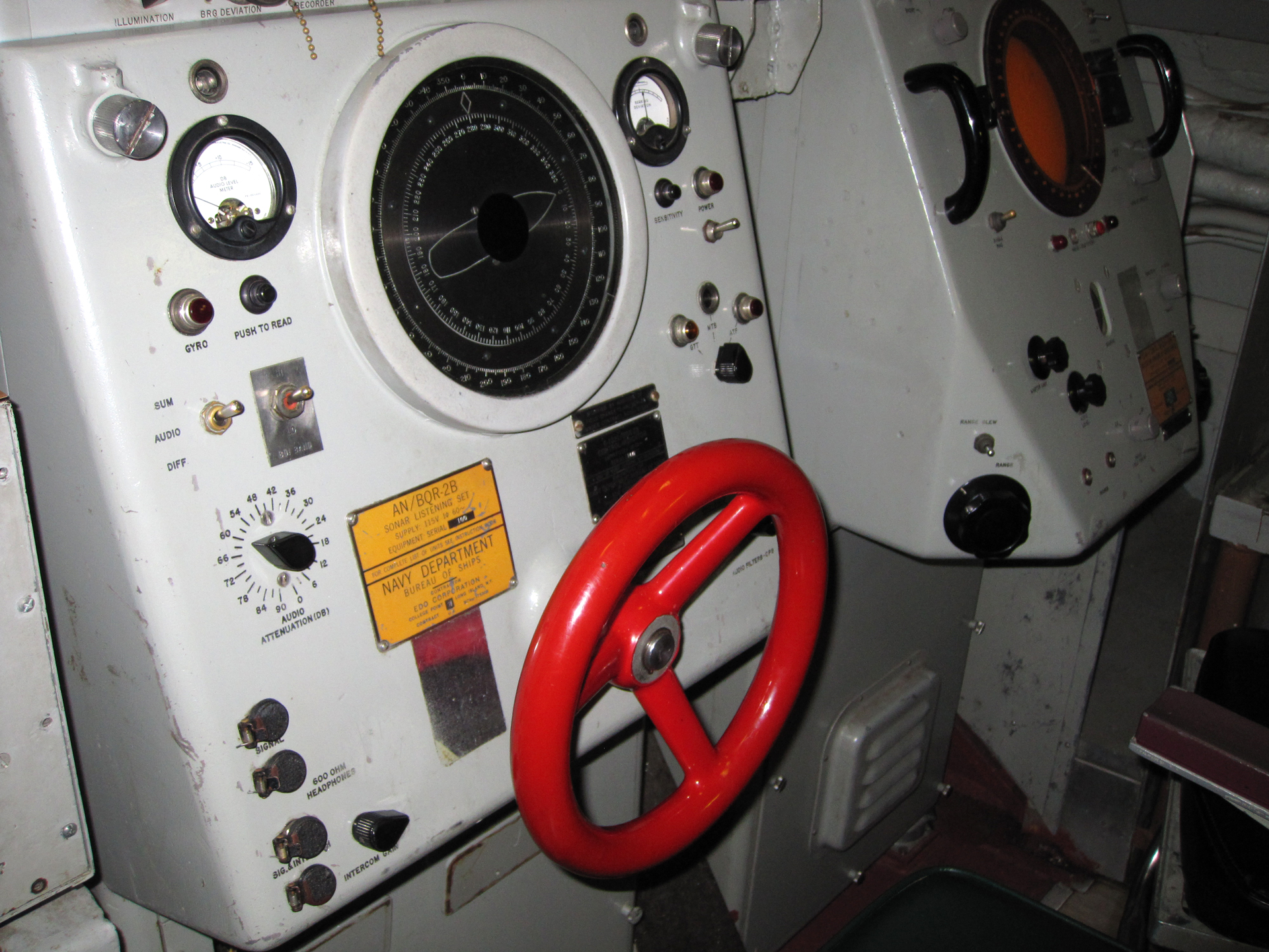

Links
PRC68, Alphanumeric Index of Web pages, Contact, Products for Sale
Page Created 25 July 2021.