Measuring EMFs
© Brooke Clarke 2021 - 2024Description
Laboratory Grade Equipment
RF Safety Monitors
Narda
Model 8210 Electromagnetic Leakage Monitor
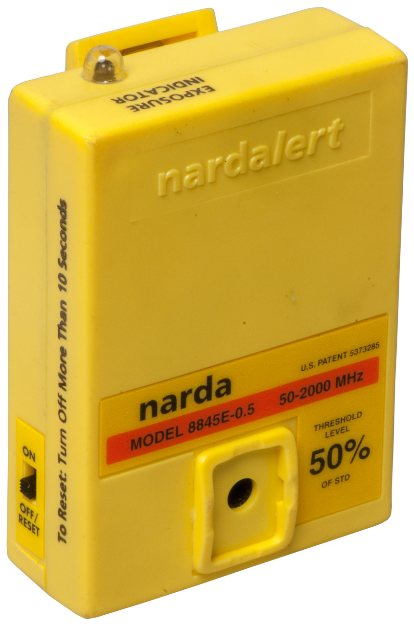
Model 8845E-0.5 Nardalert
Model 8700 Survey System
Model B86B3 Electromagnetic Radiation Monitor
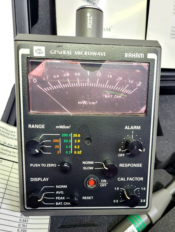
General Microwave
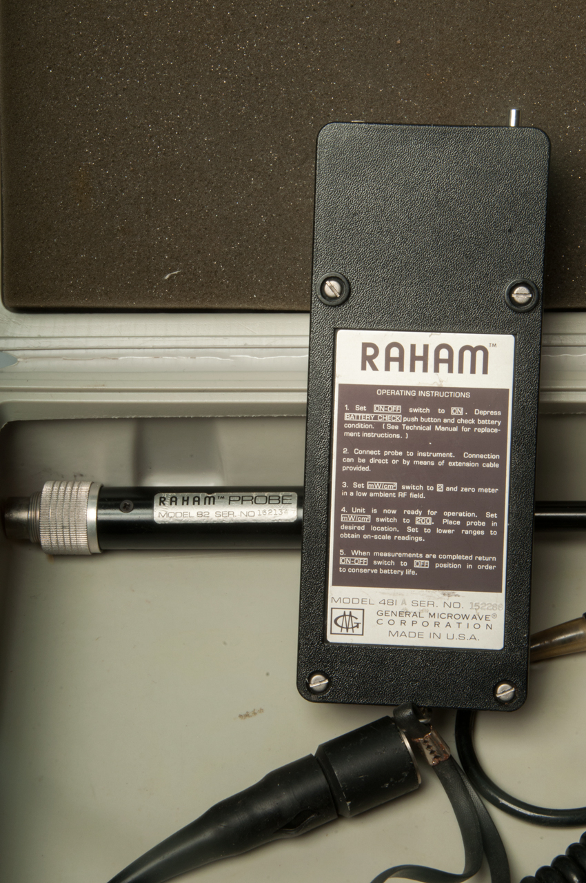
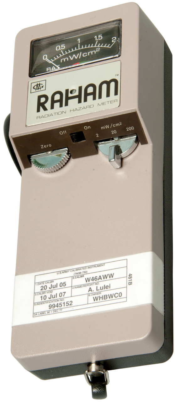
Radiation Hazard Meter (RAHAM) Model 2
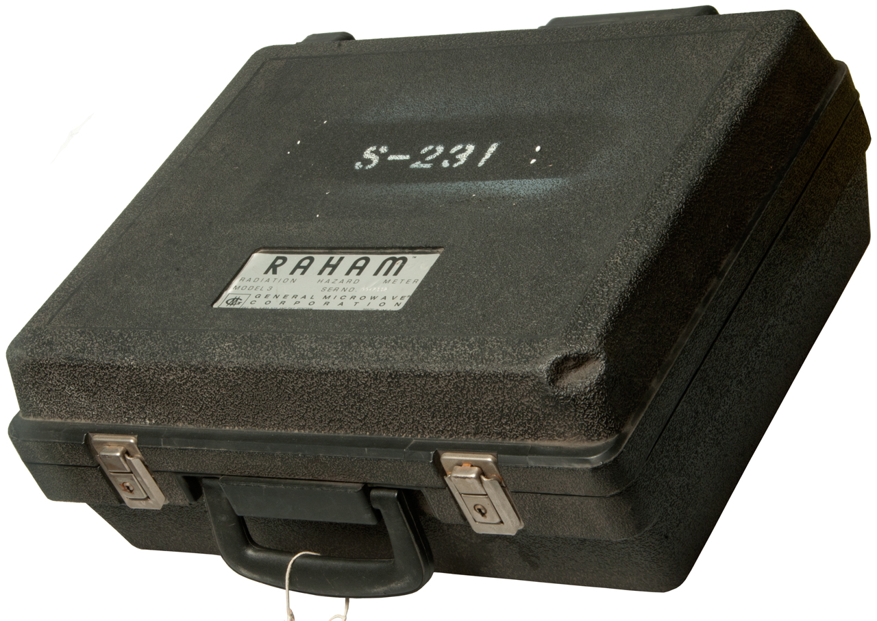
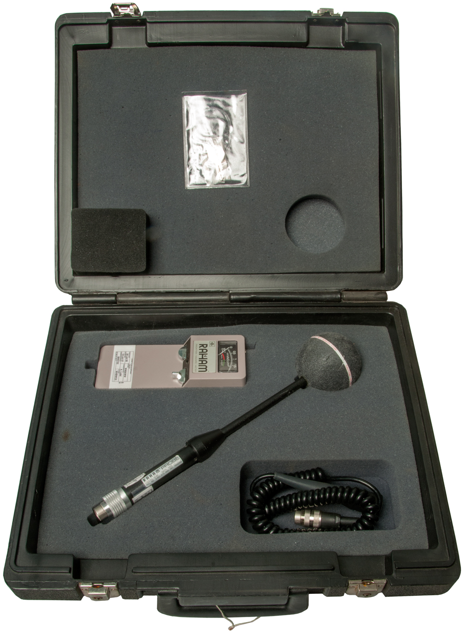
Radiation Hazard Meter (RAHAM) Model 3
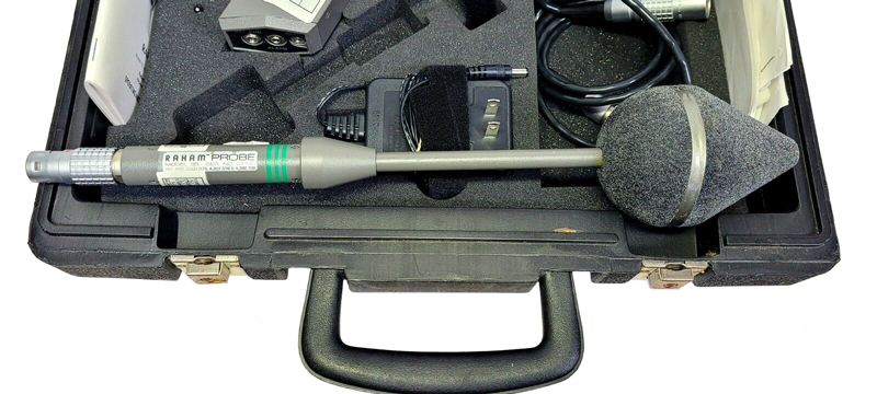
Radiation Hazard Meter (RAHAM) Model 50
RAHAM Models 10, 20, 30, 40 and 50 Radiation Hazard Measuring Systems Operating and Service Manual
Radiation Hazard Meter 84C Probe
Consumer Equipment
DT-1130 Electromagnetic Radiation Detector
Tenmars TM-196 Three-Axis RF Field Strength Meter
Photos
Patents
Related
References
Links
Background
I've stumbled on some YouTube videos showing how to use various EMF meters or reviewing them. Pretty much all of these are based on taking the manufacturer's word for what's being measured. In some cases the user is making gross errors in using the equipment.
Since I have an M.S.E.E. degree and worked a number of decades designing and testing microwave components I'd like to clear up how to measure EMFs.
First is the definition of an electromagnetic field (Wiki). Fields can be only magnetic, only electric or (both) electromagnetic. The frequency of a field can be: static (DC) or dynamic (AC). In general measuring instruments for AC fields are much easier to make than for static fields.
Wiki: Wireless device radiation and health - Bogus products = Pela, Zorb,
Description
No matter what grade equipment is used there are some things that apply to all of them.
Inverse Square Law (Wiki)
The intensity goes down as the square of the distance. So doubling the distance cuts the intensity by a factor of 4. This only applies in the far field.
Near and far field (Wiki)
The above two ideas go hand in hand since the inverse square law only applies if you are measuring in the far field. In fact a test to confirm you are making a far field measurement is to check to see if you get square law signal decrease.
For example if you have made a measurement at 1 meter from a source and increase the distance to 2 meters the signal should drop by 6 dB (4X smaller on a linear power scale). If that does not happen then the close measurement was to close to the source.
A possible exception to this is if the measuring probe is designed to work in the near field. These are typically labeled as voltage or current probes rather than EM field probes. The impedance of free space is about 120* PI or 377 Ohms (Wiki).
Pd = H2 × 377 and Pd = E2 ÷ 377
Laboratory Grade Equipment
After some reading about the Narda v. General Microwave patent law suits:
The definitive Narda patent 3641439 was for monitoring microwave ovens at 2450 or 915 MHz. It used a short dipole antenna for the higher frequency and add-on dipole elements for the lower frequency. The definitive General Microwave patent 3931573 was done in relation to an Air Force contract for a general purpose EMF measuring instrument and it did not use copper metal antenna elements but rather lossy (carbon?) elements that were not frequency sensitive. An outcome of this difference is that the Narda sensors became "shaped" to match exposure limits and the General Microwave sensors are close to flat response power density measuring instruments.
There are various scientific reasons to measure magnetic, electric and electromagnetic fields, both static and dynamic. This is commonly done using off the shelf commercial test equipment. Here are some of those areas.
RF safety Monitors
Electric field densitometers (Wiki) on this page are the RF type. There's a separate category for ELF densitometers. Some commercial personnel monitors listed.
These bear a lot of resemblance to Police Traffic Radar Warning Receivers.
Narda
Makes (made?) a number of meters and probes.
Because of the Inverse Square Law (see above) when the probe is moved toward the source it's very easy for the power to increase past the maximum limit and thus burn out the probe. Narda started shipping probes sealed in metal cans (Wiki: Faraday Cage) so that they would be known to be good. Pretty much all the 86xx series probes being sold on eBay have a disclaimer "not tested".
The Model 8611 Broadband Isotropic Radiation Meter uses all 86xx series probes.
There is a three position range switch on the meter.
Uses two NEDA 1404 5.6 Volt batteries (appears the same as A32PX 6V Alkaline)
Probe
Freq
Full Scale
mw/cm2Dynamic Range
mw/cm28652
8662B
300k - 10M
300k - 1G
2, 20 & 200
0.1 to 200
8661
300k - 1G
0.2, 2 & 20
0.01 to 20
8631
8633
10M - 300M
0.2, 2 & 20
1, 10 & 100
0.01 to 20
0.05 to 100
8682
300k - 1.5G
2, 20 & 200% ANSI RFPG
0.02 to 200% ANSI RFPG
8621D
8623D
300M - 40G
0.2, 2 & 20
1, 10, & 1000.01 to 20
0.05 to 100
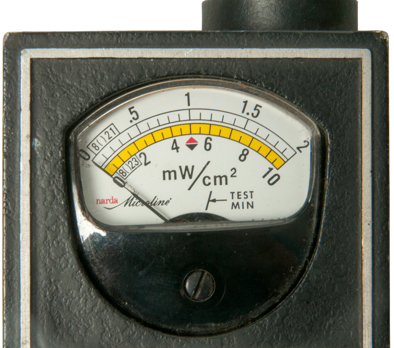
The white (top) scale marked: 0 , 1 (center), 2 (full scale)
The Yellow (bottom) scale marked: 0, 5 (center), 10 (full scale). Note the center used with to % of standard.
For example an 86()1 probe (like the 8621) will read full scale 0.2, 2 or 20 depending on the range setting.
BUT the range switch has a different meaning for probes
When the 8682 probe is used the meter reads % of Standard instead of power density. I think on the white scale, so a center needle means 1 x 100 = at the standard limit.
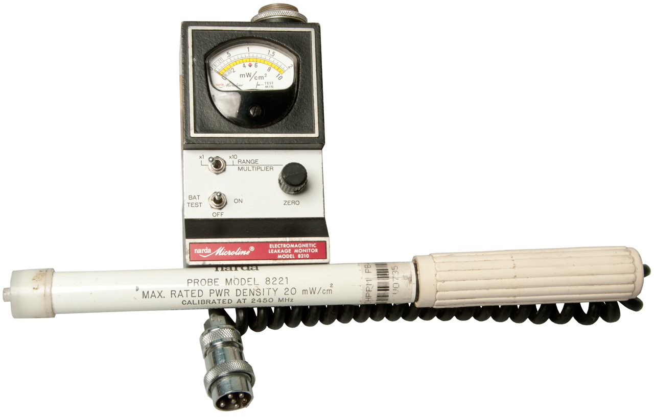
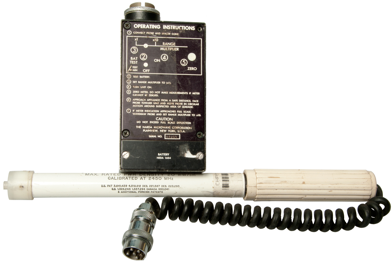
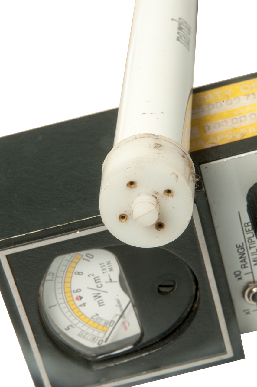
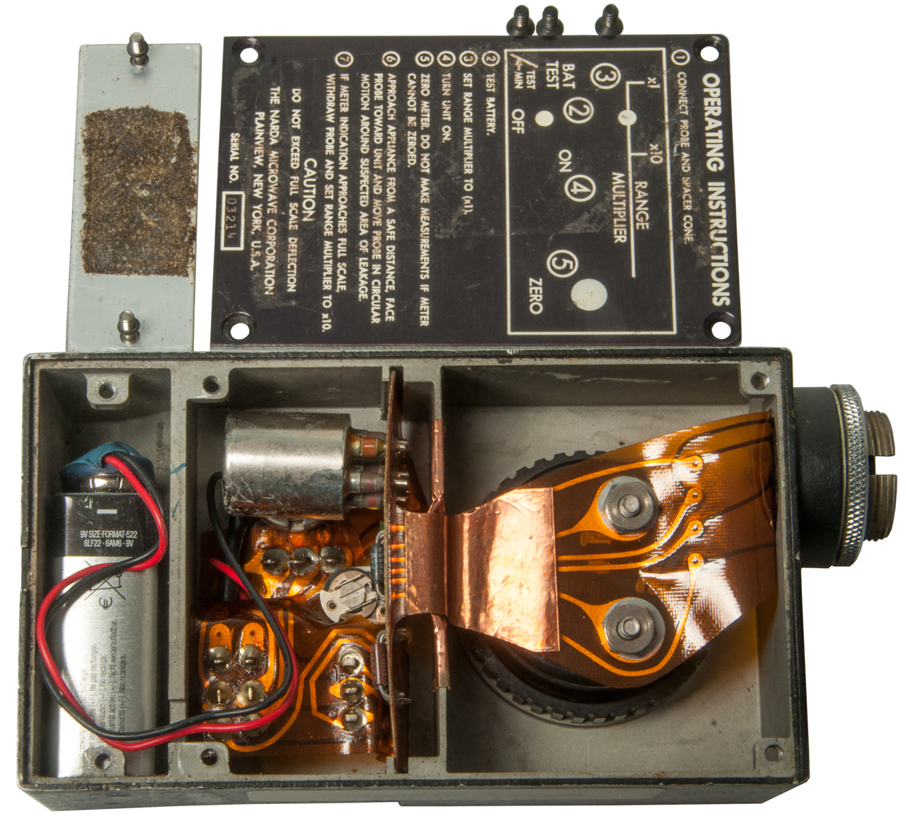
Narda Microline Model 8210 Electromagnetic Leakage Monitor Meter & Model 8221 2.45 GHz 20 mW/cm2 Probe
This may have been the first product in the line of RF monitors.
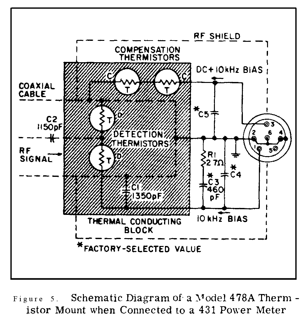
Thermistor Power Meters
The 8210 meter seems to be based on the Narda 8440 2-range RF Power Meter (the 8441 is a 3-range meter) which worked with the 8420, 8421 and 8422 thermocouple power sensors. The sensor connector seems to be the same as an HP thermistor sensor like used on the HP 432, 478, 8478 &Etc.
Pin
Description
1
10 kHz bias
2, 4, 6 & Shell
Ground
3
10 kHz bias & DC
5
n.c.
8210 Meter Voltage measurements
Switches: ON and x1 range
Volts
Mtr Gnd
2
3
4
5
6
1
+0.1
+0.025
0
+0.1 +0.1
2
-0.2
0
0
0
3
0
+0.2
+0.2
4
0
0
5
0
Switches: ON & x10
Volts
Mtr Gnd 2
3
4
5
6
1
+.01
0
0
+0.1
+0.1
2
-1.9
0
0
0
3
0
+1.9
+1.9
4
0
0
5
0
8221 Probe Ohm Measurements
Ohms
Mtr Gnd 2
3
4
5
6
1
7k3
OL
OL OL OL 2
OL OL OL OL 3
OL OL OL 4
OL OL 5
OL The probe is burned out.
Description
Uses a single 9V battery. This is used to bias the thermocouple so that if it burns out as an open the meter will go full scale instead of going to zero when there's a strong field. There does not appear to be an semiconductors in the meter box, only a sensitive meter and passive components. The meter unit should be very reliable and is repairable (unlike the probes).
This is a multiple thermocouple based RF leakage tester designed to work at the heating frequencies of 915 or 2450 Mhz. Most RF heating is done in one of the Industrial, Scientific or Medical frequencies (Wiki: ISM). Not sure why 915 was used when this meter was built. Maybe the 902 Mhz ISM band did not exist then?
The service manual for some Amana microwave ovens says to "check the oven for microwave leakage using Narda Model 8100, 8200, Holaday HI1500, HI1501 or Simpson 380M leakage monitor as outlined in the instructions. The maximum leakage level allowed is 4mW/cm2 .
An important safety feature is the inclusion of DC bias on the thermocouple sensor. Tthermocouples generate DC voltage when heated so do not need any DC bias. But when they burn out there's no DC output and the meter would indicate no power, when in fact there was so much power that it burned out the sensor. By adding DC bias the meter indicates full scale when there's a burned out thermocouple.
There are a number of probes that work at different frequencies and one or two full scale power levels (2 or 10 mw/cm2.
Probe
Freq
MHz
Full Scale
mw/cm2Max
mw/cm28()21
8221
8621
8621C
915 or 2550
300 - 40,000
300 - 26,000
2 or 20
20
8()23
8223
8623
8323
8623C
8623D
2450
300 - 40,000
300 - 18,000
300 - 26,000
300 - 40,000
10 or 100
100
Photos of 8210 and 8221
Fig 1 Range: X1 or X10
Fig 2
Fig 3 Pins numbered CW starting with Pin 1 to the right of the top notch. Pin 6 in center.
Fig 4 Pin numbers shown.
Fig 5 The 4 metal sockets are for adding to the dipole length by connecting the conical tip. BUT . . . they also allow testing the thermocouples.
Fig 6 No ICs inside only passive components.
Only 4 connector pins are used.
What is metal can on PCB? tell me.
Fig 7 Center mark between 4 and 6 indicates 100% of Standard.
The Narda 8211 Electromagnetic Leakage Monitor has a 3 position Range switch: x0.1, x1 and x10.
Patents
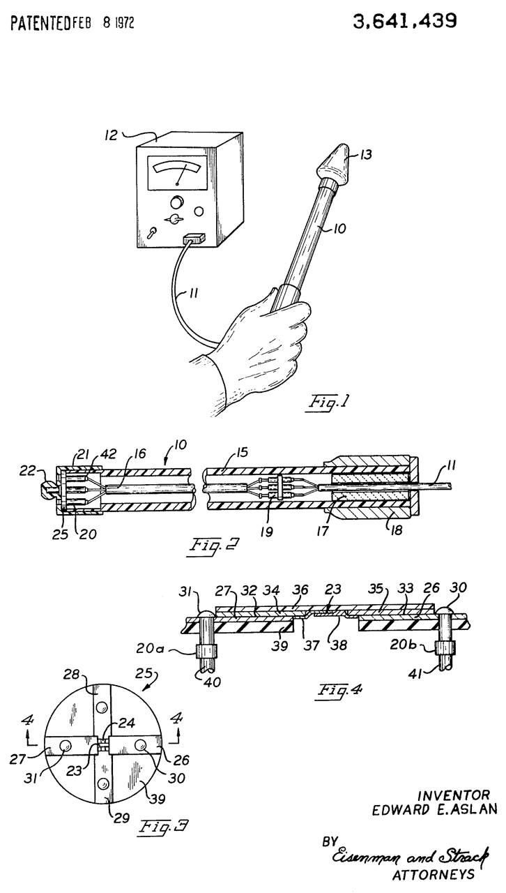
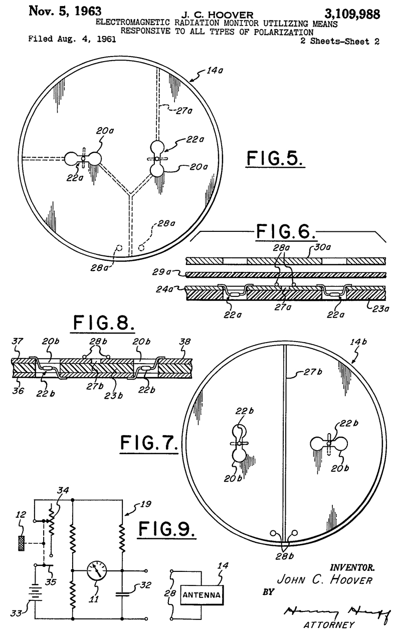
3641439 Near-field radiation monitor, Edward E Aslan, Narda Microwave, 1972-02-08, 343/703; 324/106; 250/336.1 -Probe for the Model 8100 meter
From the Narda v GM suit:
The central feature of the Model 8100 is the sensor assembly which wa constructed through thin film technology involving the deposition on a dielectric substrate of various metals by an evaporation process so as to create extremely thin files of those metals. The films were formed essentially into two parts: a dipole antenna consisting of copper, connected by silver to a thermocouple made of overlapping strips of bismuth and antimony. The thermocouple was placed in the same plane as the dipole antenna and terminated the antenna 'as a load'. The entire sensor element was approximately 3/4 of an inch in length. An identical sensor element was positioned immediately above the original one, but perpendicular to it, in essentially the same plane, an arrangement that eliminated any problem of polarized electrical fields. The remainder of the invention followed relatively conventional lines, adopting a probe format with the sensor assembly at one end of the probe, connected to a meter by semiconductive lead wires designed to draw off direct current generated by the antenna-thermocouple device."
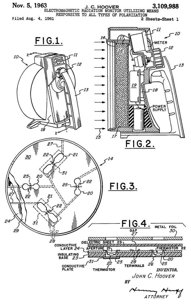
8210 meter & 8221 Probe (8211 meter & 8223 probe?)
Two thermocouples at tip of probe.
Probe : 3/4" x 12"
Sockets at tip of probe allow extending the dipole antennas so 915 MHz can be sensed. I expect that the conical tip needs to be removed when testing 2450 MHz an that's why all the units on eBay do not have the conical tip. There is also a spacer only conical tip model 81?0(B or 8)
Fig 5 & 6: In this assembly, the thermocouple 23 is again illustrated as made up of thin resistive films 37 and 38; however, it will be seen that these films extend beyond the previously described length and in effect function as the antenna as well as defining the hot and cold junction."The same as 4518912 3794914 Radiation detector employing resistive connected thermocouple elements, E Aslan, Narda Microwave, 1974-02-26, 324/95; 324/106; 343/703; 340/870.17 -
"A Radiation Detector having thin film thermocouples disposed within a plane and supported by a non perturbing probe which permits accurate measurement of an electric field in the near-field region." 915 & 2450 MHz
The same as 4518912??
4518912 Radiation detector, Edward E. Aslan, Narda Microwave, Priority: 1969-08-08, Pub: 1985-05-21, 324/95; 324/106; 343/703; 455/67.15 -
Figures 1, 2, 3 & 4 the same as in 3641439.
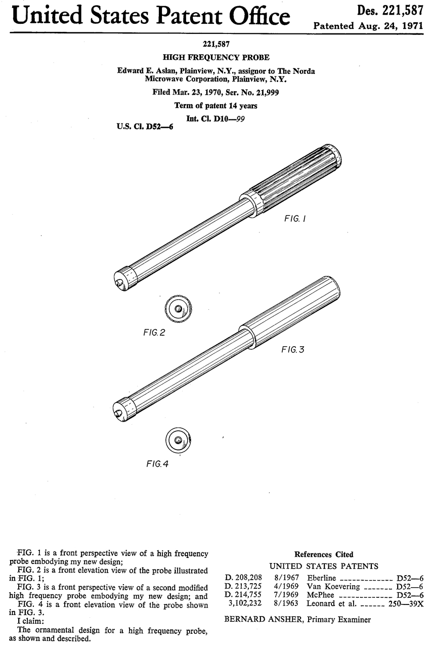
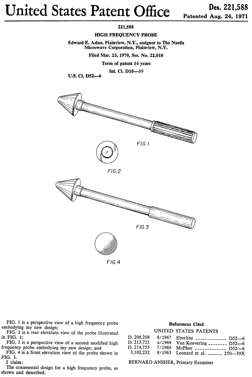
D221587 High Frequency Probe, Edward E. Aslan, Narda Microwave, 1971-08-24
D221588 High Frequency Probe, Edward E. Aslan, Narda, 1971-08-24
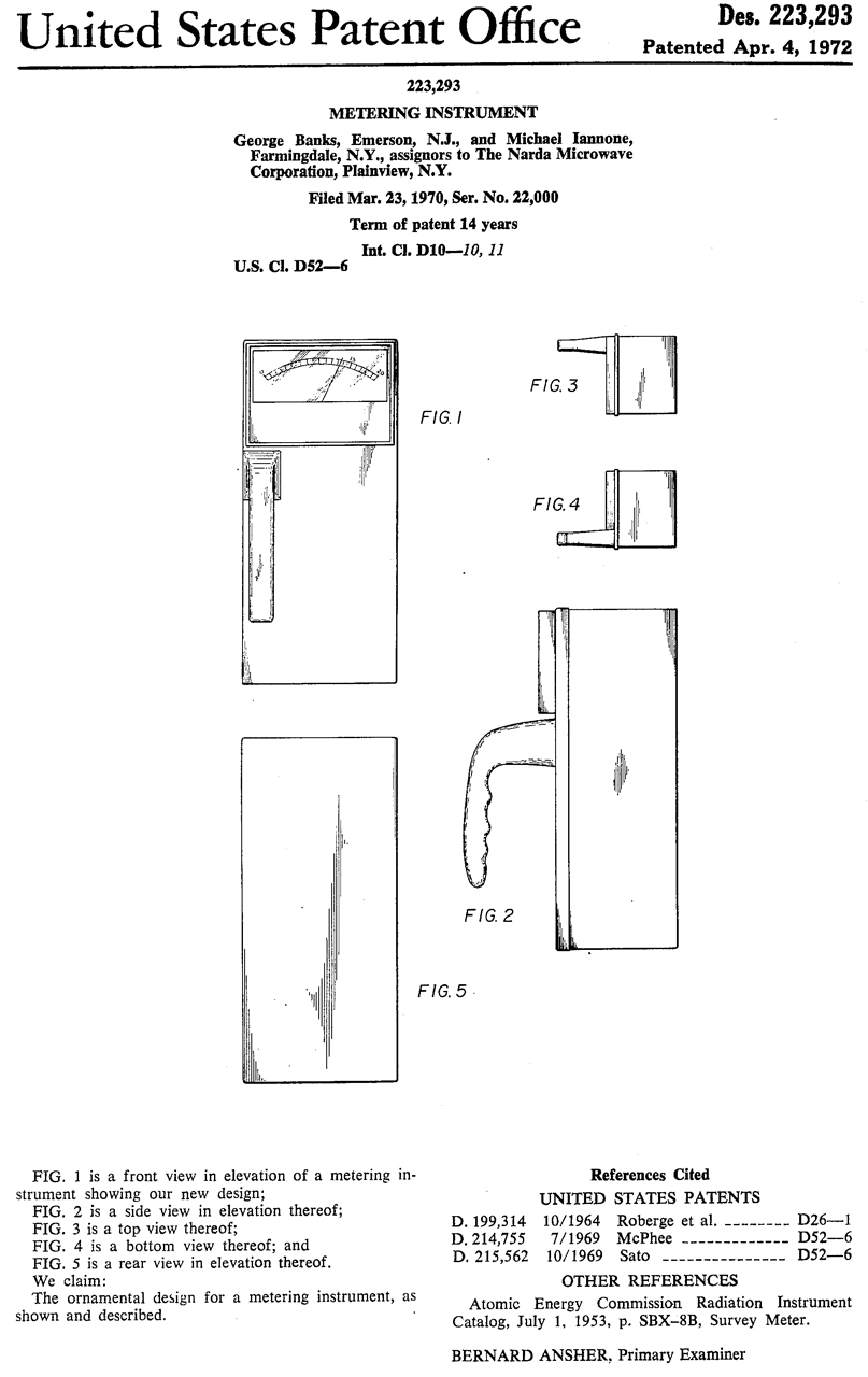
D223293 Meteriing Instrument, George Banks, Narda Microwave, 1972-04-04, - has the look of a Geiger counter except handle is on the left edge (making it unbalanced, poor design).
8616 meter, 8110
Nardalert Model 8845E-0.5 50 - 2000 MHz
Versions
Model
Frequency
GHz
Alarm
mW/cm2
8840B
2 - 18
5
8840B-01
2 - 18
1
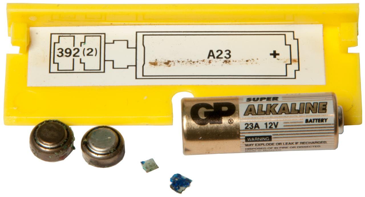
This is a belt worn unit about the size of a pager. This particular unit was stored with the batteries installed and as they corroded the battery contacts have been eaten away. I have some batteries on order (1 ea: A23 12V & 2ea: 394 1.5V) and will rebuild the battery contacts to see if that was the only problem.
2021 July 14 - After soldering new contacts into each battery compartment and installing new batteries the unit beeped when switched on, but the LED did not come on. Checking the total voltage across the two 394 button cells I only measured 1.5 Volts, it should be about 3 V. Checking each cell one measured 1.3 V open circuit. I replaced that cell with another new cell and after installing both of them the voltage across both cells measures about 3. Now when switched on the LED lights and the beep sounds. Holding this near either WiFi base station or the DECT cordless phone when it's working has no response. That's to say neither of these devices is emitting anything that's a hazard.
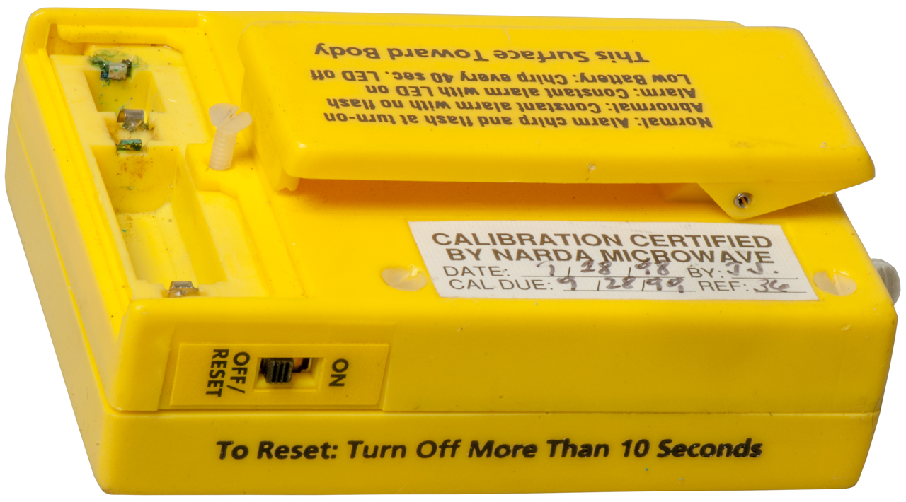
Fig 1 Hole at bottom is for
plastic tube to ear piece.
patent 5373285
Fig 2 Missing battery contact.
Fig 3 Two tabs fell out when the batteries were removed.
5168265 Personal electromagnetic radiation monitor, Edward E. Aslan, Narda, 1992-12-01, 340/600; 250/336.1; 250/395; 250/526- belt worn, plastic tube to ear
5373285 Personal electromagnetic radiation monitor, Edward E. Aslan, Narda, 1994-12-13, 340/600; 250/336.1; 250/395; 250/526- belt worn, plastic tube to ear
5600307 Surface charge personal electromagnetic radiation monitor and method, Edward E. Aslan, Narda, 1997-02-04, - Model 88nn, Fig 17: Schematic, Nardalert XT 8860, 8861, 8862, 8864
6154178 Ultra wideband personal electromagnetic radiation monitor, Edward E. Aslan, Narda, 2000-11-28, - - Nardalert XT
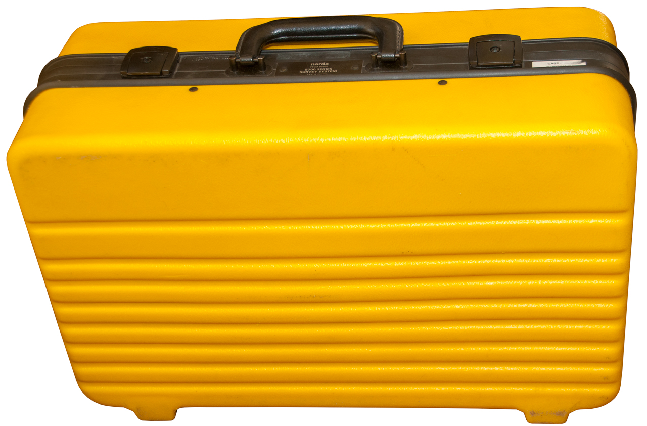
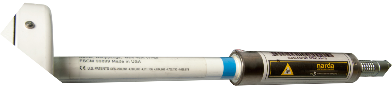
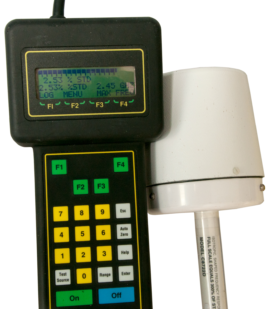
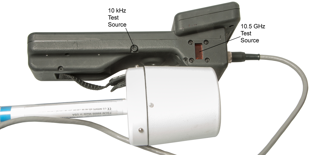
Model 8700 Survey System
This appears to be a New In Box (NIB) system. Offered at a discount price because the Ni-Cad battery pack is near dead. Keeping my fingers crossed that the sensor is functional and not dead. Pretty much all the Narda EMF measuring probes I've seen on eBay appear to be burned out.
The hand held unit has a lot of heft. It's similar to the hand held unit for the URN-502 GPS receiver. But this hand held has more features and includes specific circuitry to process the signal from the probe.
C8722D Probe
This is a shaped response probe that matches Canada's Safety Code 6. This appears to be identical to the FCC OET Bulletin 56 exposure limits. Unfortunately for shaped response probes the 8700 system only displays % of limit, not a specific power density.
Between 1.5 and 15 GHz 50 W/m2 for Controlled Environments or 10 W/m2 for Uncontrolled Environments. In a Controlled Environment the people exposed are aware of the source of RF and can avoid exposure.
One mW/cm2 is the same power density as 10 W/m2.
Photos
Fig 1
Fig 2
Fig 3
Fig 4
Fig 5
Fig 6 Patent numbers (see: table below)
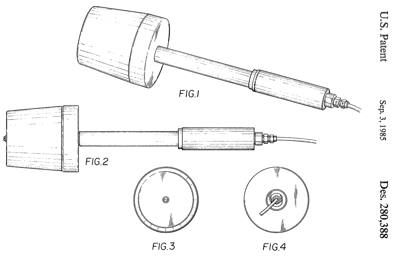
D280388
4605905
4611166
4634968
4752730
4629978
Fig 7 Test Source = ON
This confirms that the probe is working.
Back Light turned on in Battery Menu.
Fig 8 10 kHz & 10.5 GHz Test Source locations
4605905 Amplifier input circuitry with compensation for pyroelectric effects, (Intersil ICL7605 & ICL7606)
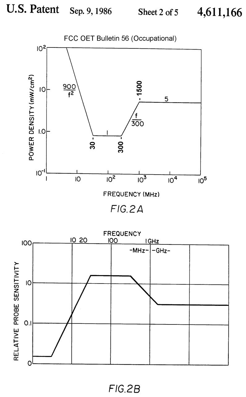
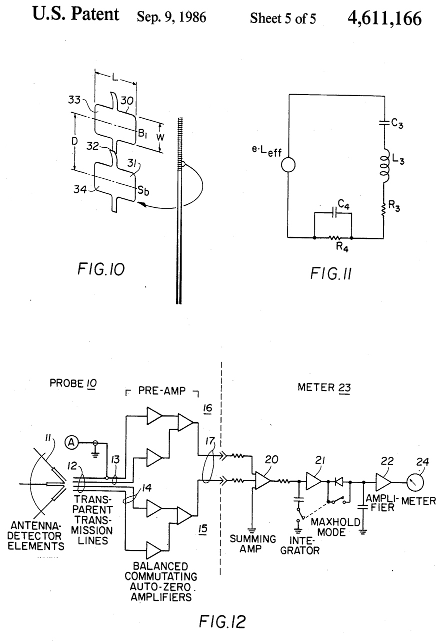
4611166 Radiation hazard detector, Edward E. Aslan, Narda, 1986-09-09, -
A.N.S.I. protection guides peak sensitivity around 100 Mhz
Fig 2A is now FCC OET Bulletin 56 Occupational exposure limits.
I have added the corner frequencies.
The probe is designed to have a frequency response that's the inverse of the exposure limit.
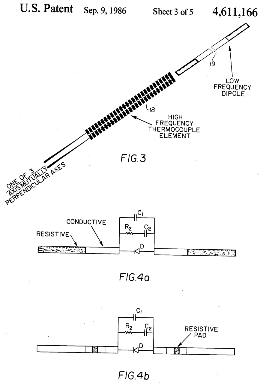
Fig 3 & $a & 4b: Electrical design to get desired response.
Fig 5 to 9: Equivalent circuits that match the desired response of Fig 2B.
Fig 10 to 12: Overall function circuits.
4634968 Wide range radiation monitor Edward E. Aslan, Narda, 1987-01-06, -
A.N.S.I. protection guides peak sensitivity around 100 Mhz
Very similar to 4611166.
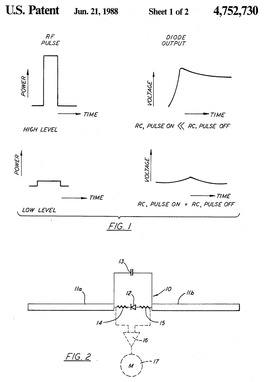
4752730 Radiation monitor diode detector with constant efficiency for both CW and pulsed signals Edward E. Aslan, Narda,1988-06-21, -
Adds pulse (the first generation probes were for microwave ovens), not they work for RADAR.
Also by using raw (not packaged) components the frequency is extended into the microwave region.
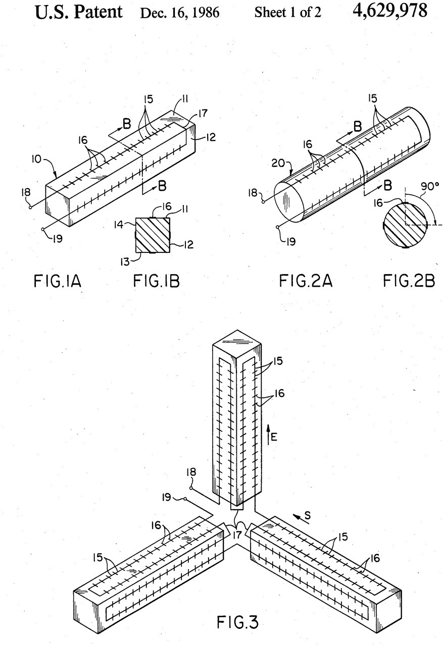
4629978 Dipole antenna Edward E. Aslan, Narda, 1986-12-16, -
"An antenna comprising orthogonal arrays of resistive thermocouple dipoles interconnected by transversely extending conductive elements of discrete length. The components are designed to create an additional response by a traveling wave effect on the dipoles along the Poynting vector to offset the falloff in dipole sensitivity experienced as frequency rises." ...constant from 12 to 40 GHz.
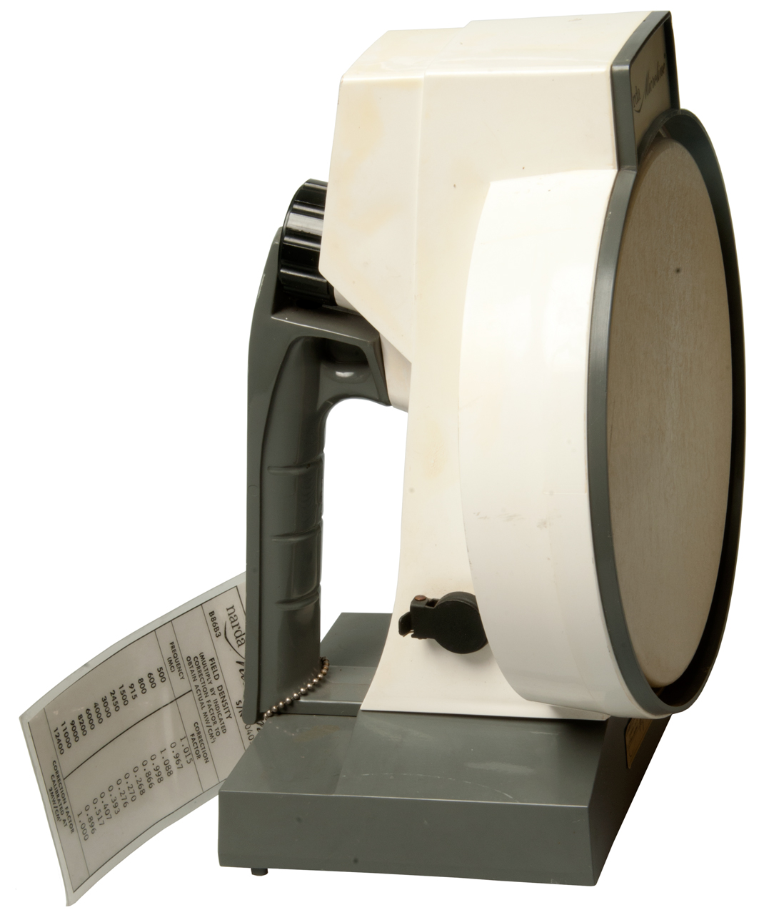
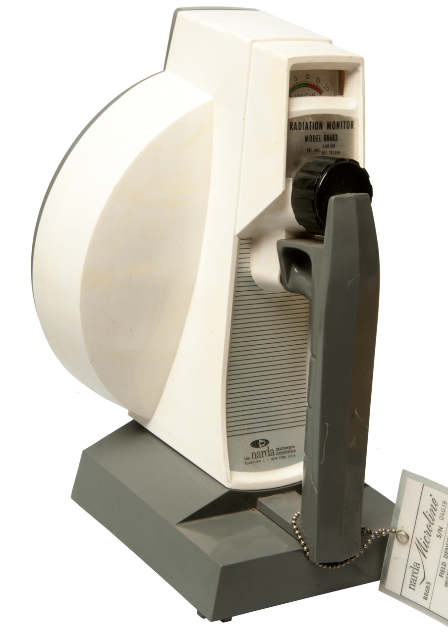
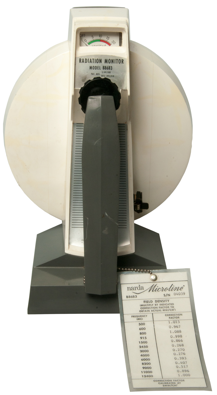
Narda B86B3 Electromagnetic Radiation Monitor
Sperry Rand appears on the patents.
Mfg
Model
Freq
Ghz
Range
mW/cm2Sperry
B86B1 .4 to 10 0 to 20 Sperry
B86B2 .4 to 10 0.5 to 20
Narda
B86B3
0.5 to 12.4 0 to 20 Ref: Nonionizing Radiation Measurement Capabilities, State and Federal Agencies, EPA, Aug 1973 (Pdf)
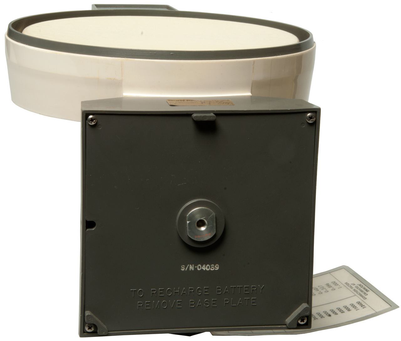
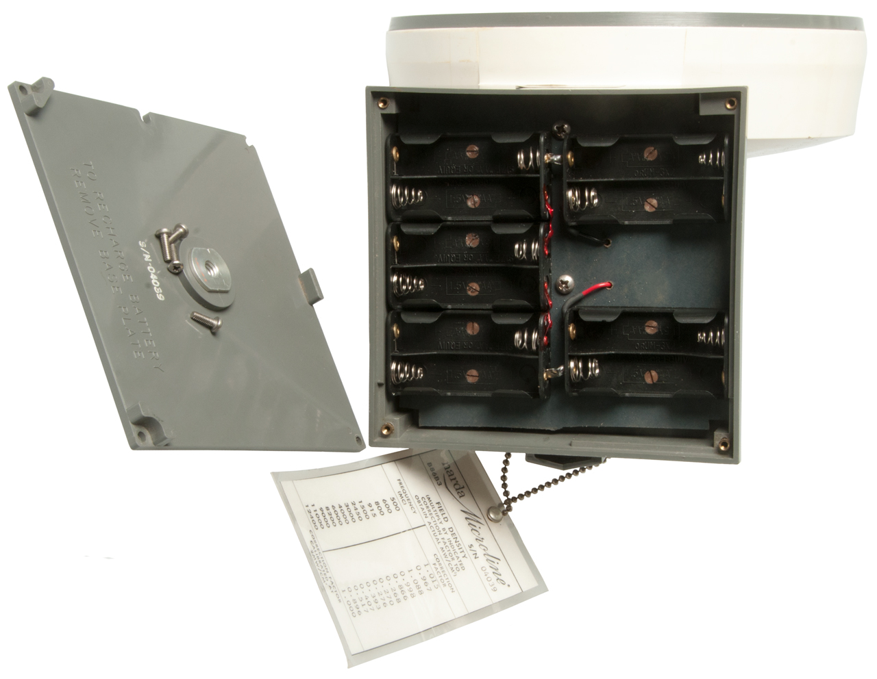
Covers 0.5 to 12.4 GHz. Powered by ten each AA batteries (maybe external DC supply TBD).
Photos
The manual is dated Feb 1970 which is well after patent 3130368 so is probably the one used here even though 3109988 is on the label.
To use a remote meter it should be 50 mV @ 1.0 mA, i.e. have an internal resistance of 50 Ohms. Or use a 50 Ohm resistor and a millivolt meter.
Connects to a 1/4" stereo phone plug. Tip: +, Sleeve: -, Ground: no connection. When the external meter is connected the internal meter is disconnected.
When 12.0 VDC is applied to the battery terminals the zero control will work. This can be increased to 15 volts and zero can be reached by turning the control CCW (toward Off), so this unit will work with either Ni-Cad or Alkaline batteries, probably L91, but did not check that.
It does not show any meter deflection on the 8700 test source. But that doesn't mean much since I don''t know the power level of the test source. Also does not show any deflection on the Wi-Fi boxes.
Fig 1 Jack: Meter out.
Fig 2
Fig 3
Fig 4 10 series connected AA batteries.
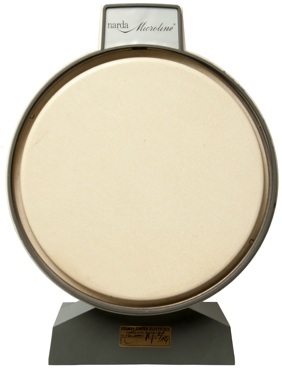
Fig 5 Narda Microline
Fig 6 Knob: Off-Zero
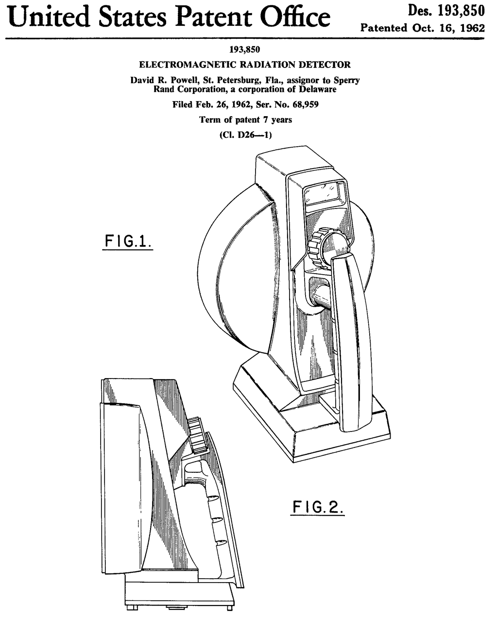
Patents: 3109988 & D193850
Patents
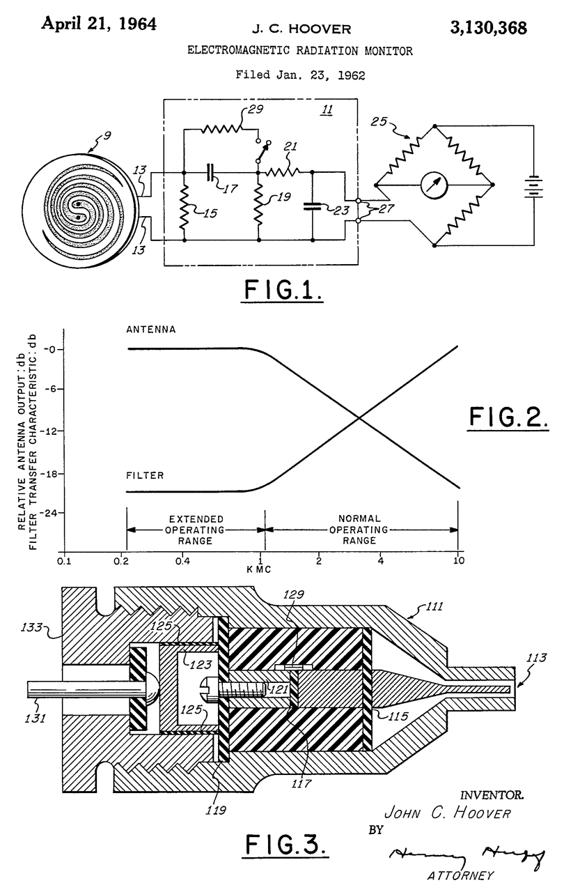
Sperry (Wiki) made airborne radar systems for W.W.II and developed power measuring patents for this new field. The early patents were for coaxial sources of power, and later the B86B1 was designed to sense power in free space, like leakage or from an antenna. You can see the progression in the below patents.
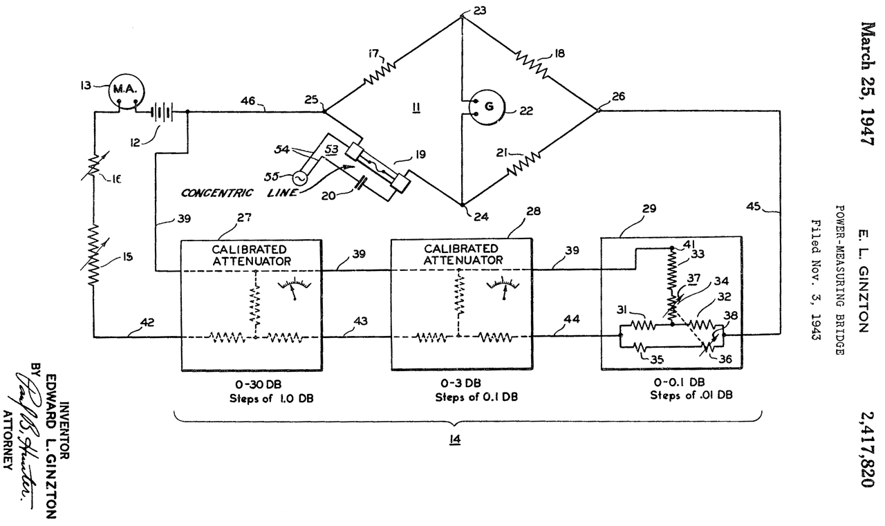
2417820 Power-Measuring Bridge, E.L. Ginzton, Sperry, App: 1943-11-03, Pub: 1947-03-25,
Uses Wollaston wire (WikiMilli) in what appears to be a cylindrical fuse glass tube as the power sensor. Wiki: Hot-wire barretter.
Also see Microwave Test Equipment: Power Meters
Also see Power Sensor Patents.
2653299 High-frequency power measuring apparatus, Edward L Ginzton, Sperry, Priority:1942-02-04, (W.W.II) Pub: 1953-09-22, -
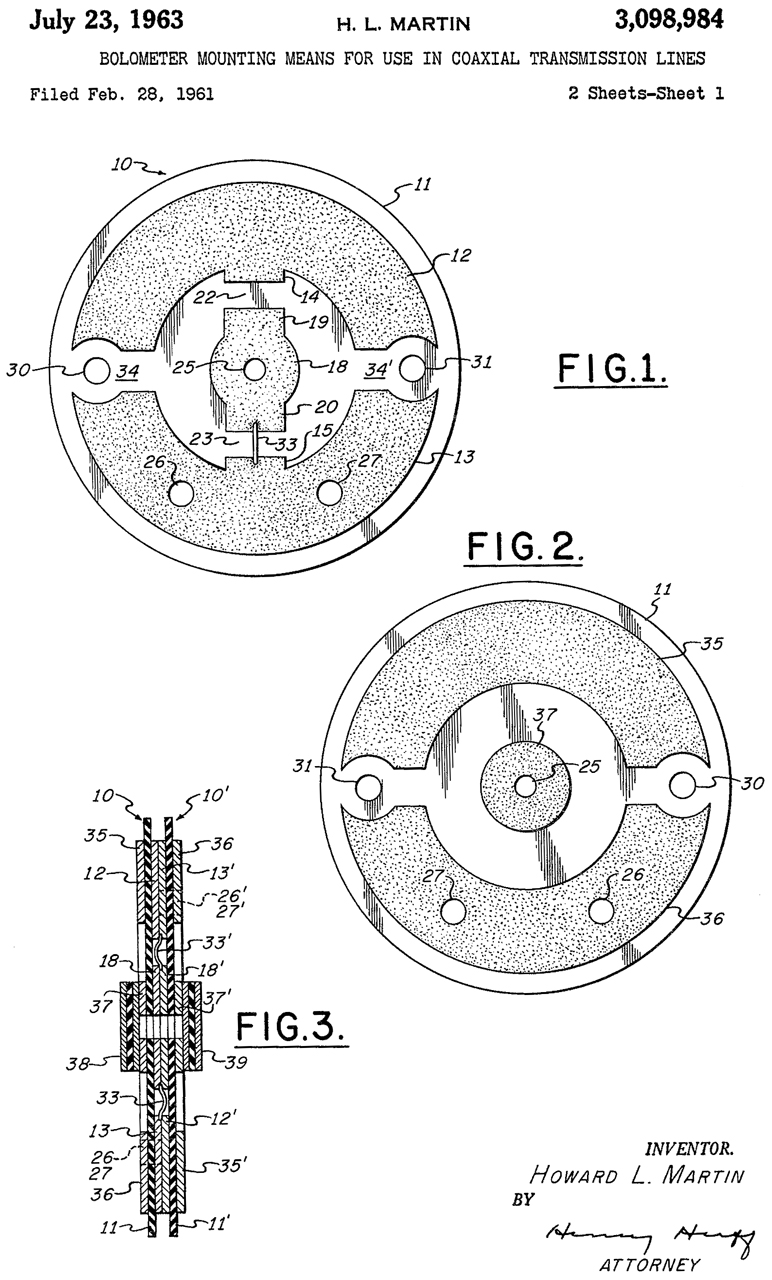
3098984 Bolometer mounting means for use in coaxial transmission lines, Howard L Martin, Sperry, 1963-07-23, -
3109988 Electromagnetic radiation monitor utilizing means responsive to all types of polarization, John C Hoover, Sperry Corp, 1963-11-05, -
The power is sensed using thermistors which have lower resistance when heated. They are non linear and come with various values of resistance at room temperature so can be matched to the antenna design.
3130368 Electromagnetic radiation monitor, John C Hoover, Sperry Corp,1964-04-21, -
Note Cavity Backed Spiral antennas (Wiki, Antenna-theory) have been around since the 1950s. A huge number of them were used in wideband radar warning receivers.
Antenna-theory: Spiral antennas -
D193850 Electromagnetic radiation detector, David R. Powell, Sperry Rand, 1962-10-16, -
Antennas
Antennas (Antennas, Wire Antennas, Wiki) are a key element in all the commercial testing. For communication antennas are optimized for transmitting or receiving a signal. But for the following tests the antennas are optimized to provide a known field strength over some specified frequency range. These typically are very expensive even on the used market.
But communications antennas can be used for testing where signal strength is the key parameter, but they need to be calibrated at the frequency and separation of use.
Receivers
Spectrum Analyzer
I'm using the word "receiver" in a very general way to mean something that takes an input signal displays its magnitude and optionally its frequency. A very versatile device is the Spectrum Analyzer (Wiki). See: Agilent E4404B ESA-E 9kHz - 6.7 GHz, HP 4395A 0 to 500 MHz, HP 71100A 2.9 GHz, Avcom PSA-45D Portable TVRO. The better units have marker peak search that displays the frequency and amplitude of the signal. But to convert the amplitude (typically dBm) into field strength you need to have some calibration data for the antenna.
Communications Receiver
Communications receivers do not have signal amplitude calibration, but some have an S-meter (Wiki). The IARU standard for a 50 Ohm input receiver as S9 = -73 for HF and -93 dBm for VHF. And one S unit should be a 6 dB change (2X voltage, or 4X power). But unless you calibrate your receiver you will not know if it meets these standards.
See: Cubic R-3030, MacKay Dymek DR33, JRC NRD-545 Receiver, ICOM R7000.
Field Strength Meter
The idea (Wiki: FS meter, has simple equation for V/m from distance and power, also see Wiki: Path Loss) is to measure the field strength of a known signal to see how well it's being transmitted. These can be relative reading, like the Army ME-61, or a calibrated measuring set, like the Stoddard URM-6.
Field Strength Probe
When a concern arose about RF field strength companies developed portable probes to directly measure RF field strength. Narda was a pioneer in this area, see patents below.
EMC
EMC (Wiki) testing is an example where known fields are generated to see what happens to the device under test. This mainly involves signal generators, power amplifiers and antennas.
I interviewed for a job where they were going to build an Anechoic chamber (Wiki: Anechoic chamber, Faraday Cage) large enough to hold a car, truck or semi tractor. There have been a number of cases where a strong signal causes a safety related malfunction.
LA Times: Ordinary Radio Waves Allegedly Can Knock Down Combat Copter, NOV. 9, 1987 - Illegal "trucker" high power CB radios cause UH-60 tail fin to move.
To test the integrity of a SKIF (Wiki) or shielded room a transmitter can be placed inside and a receiver outside tries to hear it. See: Shielding Integrity Monitoring System.
EMI - RFI
EMI (Wiki) testing is very similar to EMC testing. In both cases they are looking at both radiated and conducted paths for the problem. The RF-204 is a component tester that works be sensing RFI that shows up when the component is tapped with a rod.
Tempest
Tempest (CEI test receivers, Wiki) "...referring to spying on information systems through leaking emanations, including unintentional radio or electrical signals, sounds, and vibrations." Equipment, say a teletype machine, may have the electrical signals encrypted, but the electromagnets generate radio waves when turned of and off and by listening with a radio someone may be able to see the plain text.
The Cathode Ray Tube (Wiki: CRT) generates radio signals that can be picked up and used to reconstruct the image (Wiki: Ean Eck phreaking).
Magnetic
There are a number of variations such as static (DC) fields and dynamic (AC) fields, each requiring a different measuring instrument. There are weak DC fields, like the Earth's field, that require sensitive instruments and strong fields, like permanent magnets, that can be sensed with simpler instruments. AC fields, like from the AC power mains are very easy to measure.
Alpha Labs Model 1 & LakeShore Model 4060 Zero Gauss Chamber - AC or DC, low range is 1999.9 Gauss full scale, so the Earth's field can just be seen.
HT20 2000 mT Magnetic Flux Meter - Hall Effect (Wiki) so not very sensitive.
GE Gauss Meter & Reference Magnet - all mechanical construction from 1952
AMY6 Magnetic Polarity Tester - handy for use with permanent magnets (I use it a lot more than I thought when purchased)
Helmholtz Coil & Fluxmeter - M3 Coil Magnetic Survey Instrument (used for surveying Earth's field) - Annis M25 Pocket Magnetometer ( -0.5 to 0 to +0.5 Gauss range works with Earth's field) -
Walker Scientific MG-3D Gaussmeter - Hall Effect type - F.W. Bell 640 Incremental Gaussmeter -
HP 428 Clip-on Milliammeter Magnetometer - while this instrument is set up as a clamp on DC current meter, it is really a Flux Gate Magnetometer.
General Microwave
General Microwave set out to fulfill a government contract to measure field strength over a broad range of frequencies and so decided to use non metallic antenna elements. This resulted in a flat frequency response above about 1 Ghz which is very different than the Narda design.
Samuel Hopfer worked for Polytechnic Research and Development (Radio Museum: PRD) in the 1950s on power measurement and holds a number of patents for that work. Around 1970 he changed to General Microwave where he continued working on the measurement of microwave power.
Narda sued GM for patent infringement in relation to Narda patents: 3641439 (valid but not infringed by GM), 3794914 (not valid because of GM patent 3931573), Narda D211588 (invalid filed too late). Narda's models 8300 & 8600 infringed GM's patent 3931573.
Model 1 introduced in 197 based on the 3931573 patent.
Model 2 ?
Model 3 introduced in 1976 used serially connected thermocouples.
Radiation Hazard Meter (RAHAM) Model 2
This set consists of: The Model 481 Meter, Model 82 Probe, Extension Cable, Carry Case with missing foam.
Neither the probe or meter has a suffix letter.
Fig 1
Fig 2 Factory bottom foam has disintegrated.
The plastic hinge type latch has broken off.
Fig 3
Model 82 Probe and 481 meter
Fig 4 Someone installed a couple of AA batteries.
I very much doubt they would work.
Fig 5 Notice (+) polarity markings in case.
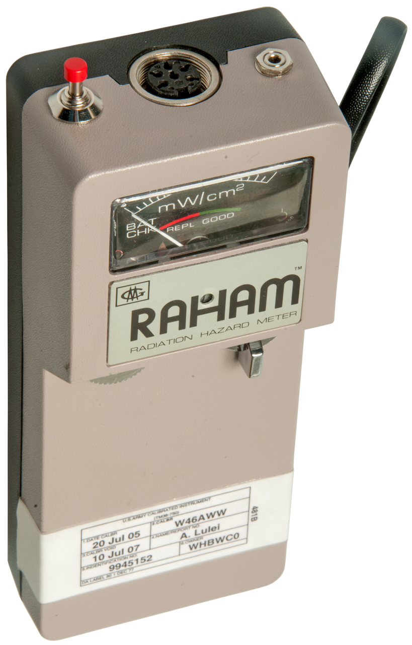
Radiation Hazard Meter (RAHAM) Model 3
This set consists of: The Model 481B Meter, Model 83B Probe, Extension Cable, Carry Case with key.
MAJOR missing items are:
I believe the reason these are being sold on eBay for low prices is that the batteries have gone dead and it will take some engineering to figure out how to replace them. I saw what appears to be a New In Box unit on eBay and the two batteries appeared to be wrapped in plain white plastic, like mine with no marking. They were in a plastic bag with a label, but when that bag is lost there will be no way to know how to reorder the batteries.
- instruction book
- Information on batteries. (One eBay seller thought that they were AA batteries. But this is WRONG).
Controls & Indicators
On/Off Switch.
Knob to Zero the meter
Range Switch: 2, 20, 200 mW/cm2
Jack
The jack may be a 2.5mm mono phone plug.
I'm guessing the jack is for an external voltmeter to record the signal strength.
Recorder Output: 0.124V full scale into min resistance of 100K Ω
Red Button
Not sure what the red button does.
Battery
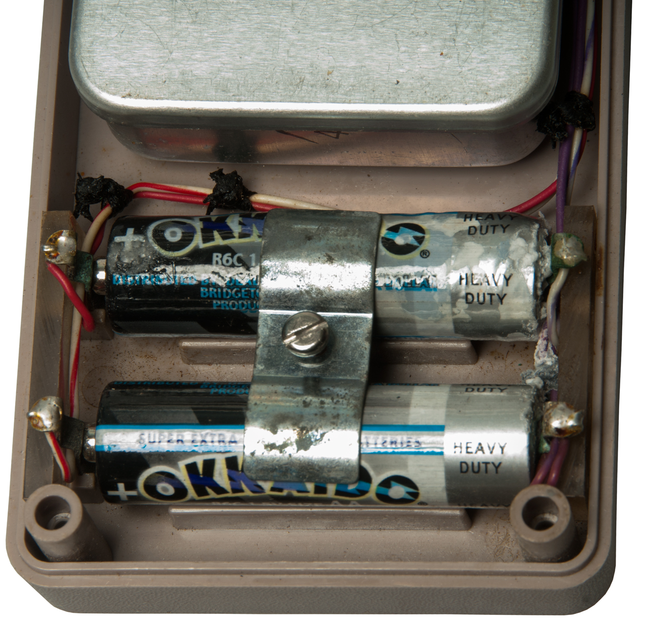
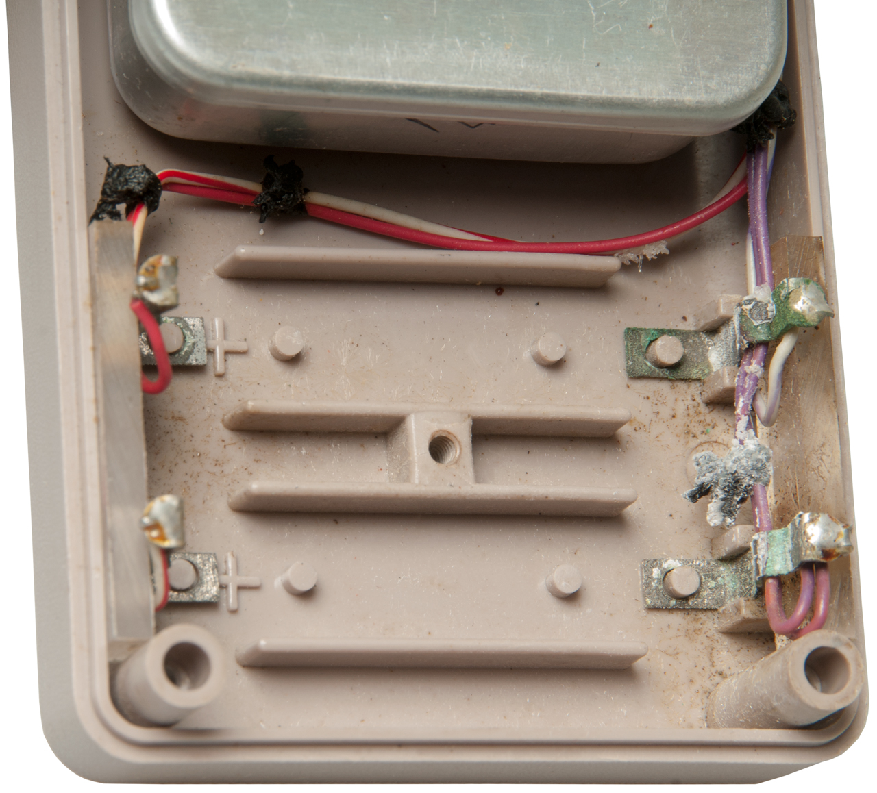
Each of the two batteries consists of a stack of 3 each LR50 batteries (Energize: EN1A.pdf). I.e. each battery is 4.5 Volts. The Flat end of an LR50 battery is (+) and the tit end is (-). Both batteries are installed with the (+) end to the left. The plastic case has (+) marks under the left end of each battery. They are connected as a split supply with a Common (+) and (-) terminal, see Fig 9 below. The dots in Fig 9 were located using a fingernail to find the joints between the LR50 cells. The batteries are held in by spring clips, they are not soldered in. They are Alkaline primary (non rechargeable) batteries so no need for a charger.
There is no marking on the batteries, so they were a secret sauce only sold by whoever sold the meter.
In Fig 7 you can see the LT1002 Dual Matched Precision Operational Amplifier (LT: LT1002.pdf) Specified to work from +/- 3 to +/- 18 V, so it will NOT work on 1.5 Volts.
Fig 1
Fig 2 The plastic pocket in the lid is for the calibration table. I have the key in it now.
Fig 3
Fig 4
Fig 5
Fig 6
Fig 7 LT1002CN
Fig 8 Meter & Probe
Probe has "patent 3931573"
Fig 9
Operation
2021 July 13 - With fresh batteries installed and the red button pressed the meter goes into the battery good (green) zone. With the probe attached directly to the meter and in the 200 mW/cm2 range, it is easy to adjust the meter to zero. In the 20 mW/cm2 range it is a bit tricky to get a zero adjustment, but in the 2 mW/cm2 range it is impossible. The best you can do is get the meter to read on scale and near zero.
When in the 2 mW/cm2 range and you move around the meter deflects probably due to electric field differences. When you stop moving the needle settles down. So far I have only seen deflections of a few small tick marks when near the Wi-Fi routers or a DECT cordless phone, i.e. the field strength is around a few tenths of a mW/cm2.
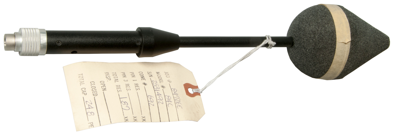
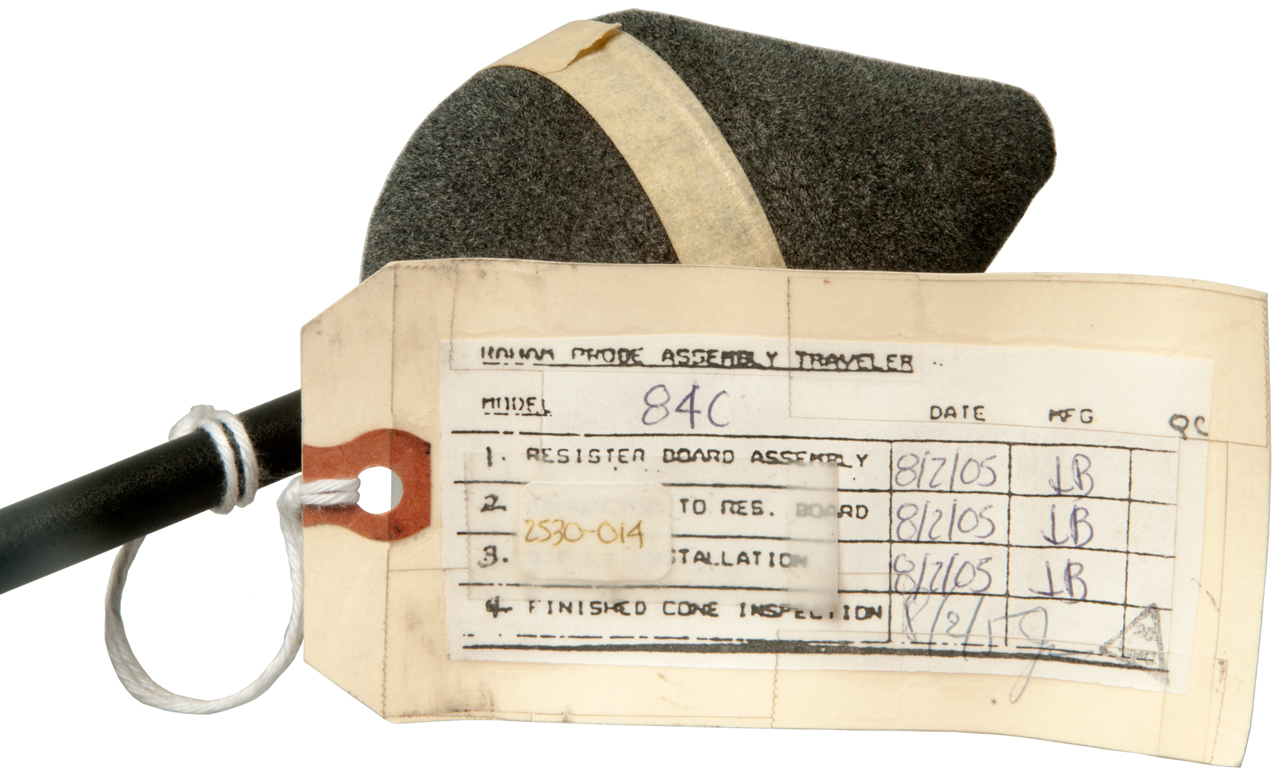
Radiation Hazard Meter 84C Probe
This is, I hope, a refurbished probe.
Here is data from a Cal Table for a model 83B probe.
You can see it's fairly flat from 1.2 GHz to 18 Ghz, i.e. better than =/- 20%.
Freq
Mult. Fac.
0.2 MHz
na
2
na
27
na
100
na
300
1.82
1.2 Ghz
0.95
2.45
1.06
3.8
1.11
8
0.78
12
0.88
18
1.15
26.5
na
Fig 1
Fig 2
Meters
There are sets Model 1, 2 &3.
Meters 484, 484A, 484B, 495
NSN
Description
6625-01-229-7429 RAHAM 4A
6625-01-514-7753 481B
6625-01-437-6236 495
6625-01-068-1485 Model 3?
6625-00-397-4197
495
Frequency range 200 khz to 40 ghz;
power density range 40 db;
batteries built in rechargeable type;
full scale reading 0.02, 0.2, 2, 20 mw/cm;
power density meter model 495; includes audible alarm when power density exceeds the selected level;
3 operational modes normal, peak and average;
can be operated from 115/230 power source;
response time 1.5 second normal or 3 seconds slow;
includes battery charger
Model
Meter
Probe
Freq
Manual
Batteries
Military
TM
1
481
0.3 - 18 GHz
BA-1098
ME-513/U
NSN: 6625-01-068-1485
1981
11-6625-2988-14
11-6625-2988-24P
2
3
4
4A
4B
4C
484
84C
200 kHz - 40 GHz
RAHAM484UserManual.pdf
TR133
Mercury
4.2 V.
Probes
The connector may be a version of a circular DIN (Wiki). These are normally push to mate pull to separate. But for this application a custom screw on housing is used. I have on order male and female 6-pin DIN connectors to see if they fit and for use in electrical testing.
Set
Case
Latch
Probe
meter
Button
1
81A
1
1 plastic
81
481B
2
82
481
2
2 metal
?
481B
2
1 plastic
main hinge also broken
3
2 metal 83B
481B
3
83B
481B
4
2 metal 84B
484
Chrome
4A
84C
484
?
Cal Factors @ 27.12, 130, 900 & 2450
Patents: 3931573, 4207518 & 4392108
50
2 metal 95
495
91
92
93
94
95
84C Probe Check
Terminals
Resistance
1 & 3
1.5M (forward)
Open (Reverse)
4 & Case
short
5 & 6
100 to 5,000
Probe pins are numbered 1 to 5 CCW starting CCW from keyway with the center pin No. 6.
There is a "Test Fixture" for the 484 meters that supplies 0.02, 0.2, 2 or 20 mW/cm2 signals to test meter on pin 1 (+) and pin 3 (neutral).
There is a resistance of 1408 Ohms between pins 5 & 6. Pin 4 is chassis ground.
The connector for the "Test Fixture" might be 91-T-3403-9.
The cable connectors might be: Amphenol 91-T-3400-1 and 91-T-3403-9
Radiation Hazard Meter (RAHAM) Model 50
These photos from a sold eBay auction. Photos with permission of seller canalresale101.
This is a major improvement in the meter from the prior model 1, 2 &3 sets.
495 Meter
Four range positions work with three probe colors to cover 0.02 to 200 mW/cm2.
Many other features including rechargeable battery.
Fig 1
Fig 2 Cal Chart 3 kHz - 40 GHz?
Fig 3
Fig 4 Label of 495 meter
Fig 5
Fig 6 95 Probe
RAHAM Models 10, 20, 30, 40 and 50 Radiation Hazard Measuring Systems Operating and Service Manual (Archive.org)
Hopefully this will answer some questions about the batteries. Specifications to allow replacement and information about wiring of charging connector.
Did not answer these questions since it's all about models based on the 495 test meter and 90 series probes.
This manual goes into some detail on the 495 meter and the 91, 92, 93, 94 & 95 probes.
The manual does NOT mention which probes go with which model numbers.
Model
Freq
GHz
Polarization
10
0.3 - 18
anisotropic
91 92
20
0.1 - 3
30
.3 - 18
40
200 kHz - 40 GHz
isotropic
93 94 95
50
200 kHz - 40 GHz isotropic There is a schematic for a "test fixture" that simulates a probe to confirm operation of the 495 meter. It uses a LEMO FG8308W0060 connector.
This is a different probe connector than the one used on the single digit model meters.
The "test fixture" supplies voltages to the meter simulating 0.02, 0.2, 2 or 200 mW/cm2 as selected by a switch.
Patents
1923916 Field strength measurement for ultra-short waves, Rene H Darbord, International Communicatioins Lab, 1933-08-22, - - antenna & power sensing (thermocouple)
2106768 Filter system for high frequency electric waves, George C Southworth, AT&T, 1938-02-01, - Fig 7a: thermocouple based
2496879 High-frequency detection and measurement device, James M Lafferty, GE, 1950-02-07, - bridge (bolometer) thermocouple based - light or radio
3147436 Symmetrical thermopile circuit for measuring electromagnetic wave energy, Samuel Hopfer, PRD, 1964-09-01, - coax power head thermocouple/thermopile
3641439 See Narda patent 3641439 - antenna & power sensing
3384879 Diode-matrix device for data storing and translating purposes, Stahl Kurt, Vogel Ruth, Langer Jurgen, Kielgas Hans, Brown Boveri, 1968-05-21, - diodes used for data storage. But the arrangement might be used for a power sensor?
3931573 Radiation detector, Samuel Hopfer, General Microwave, 1976-01-06, -
Comments on 1923916 & 3641439: "This instrument type suffers from one or more of several disadvantages. Realizable antennas place limitations on bandwidth, particularly in the lower frequency ranges and do not provide a constant “effective aperture." One instrument employs seven antennas to circumvent this problem. In addition, antennas employ conducting surfaces which, because of interaction effects, degrade the reliability of near field measurements. Since it is to be anticipated that people will be increasingly exposed to radiation fields of many frequencies, a broadband instrument is desirable which is practical in size. More over, the instrument should be generally effective without limitation on its orientation to the polarized radiation field."
You can see in the patent plot that they were trying to get very flat response out to 18 Ghz. The report I read said below about 1 Ghz the response rolled off, but above that it was fairly flat.
4207518 Broadband radiation detector with diode elements, Samuel Hopfer, General Microwave, 1980-06-10, -
4392108 Broadband radiation detector for microwave and lower frequencies, Samuel Hopfer, General Microwave, 1983-07-05, -


Consumer Equipment
EMF measurement (Wiki) is a name commonly associated with consumer equipment. The Wiki page has a table of consumer grade EMF meters.
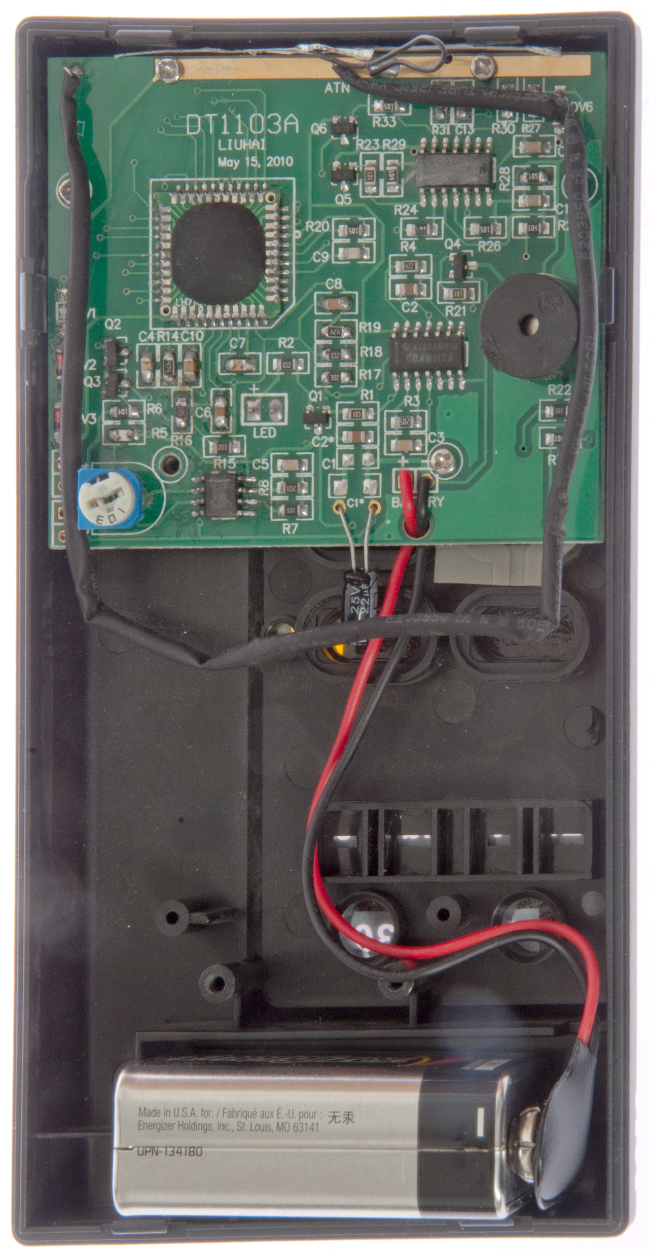
DT-1130 Electromagnetic Radiation Detector
This unit has a digital display but there are no units!!!! So it just for show or fooling someone.
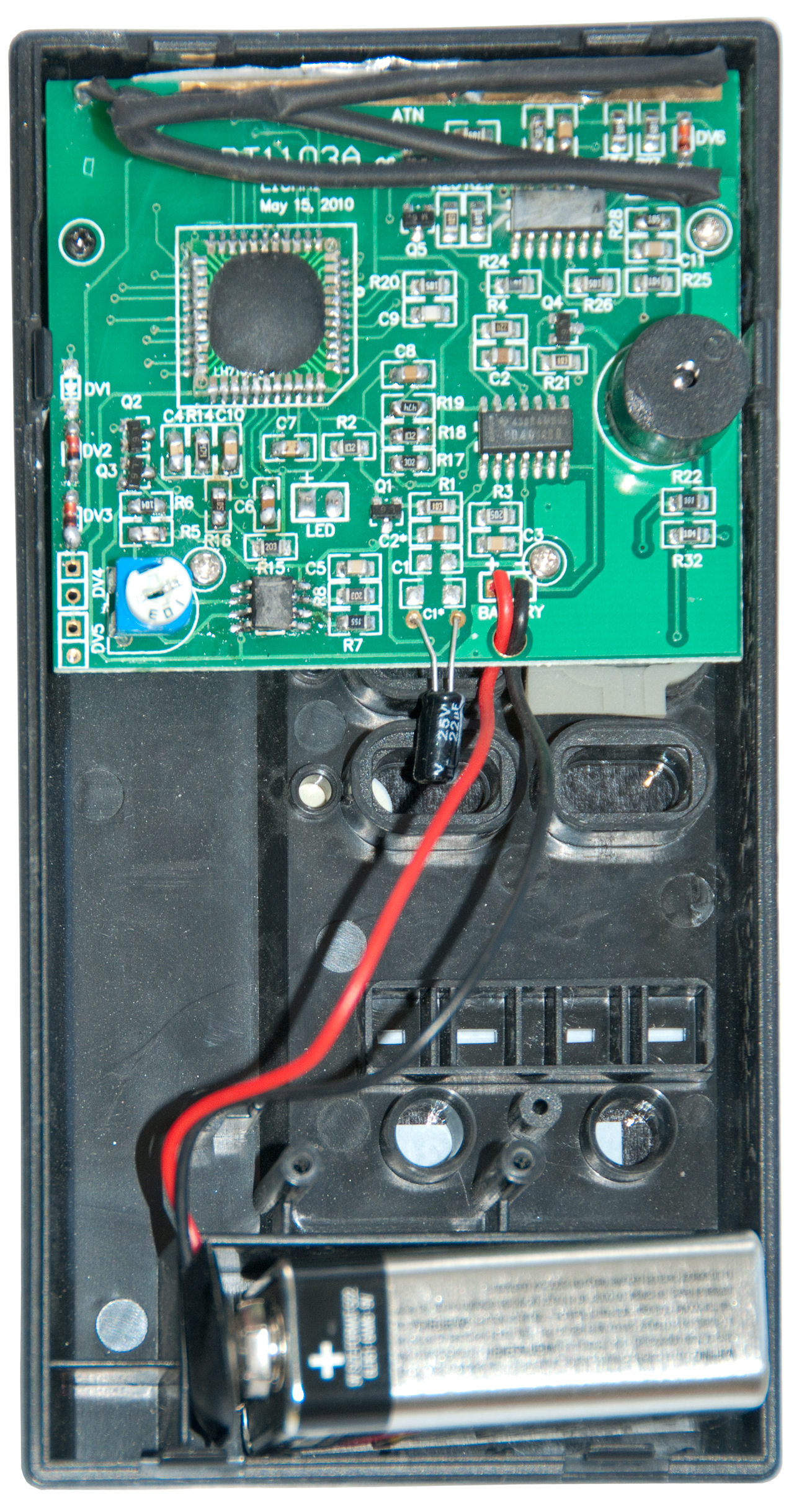
Internal PCB Marking:
DT1103A, Liuhai, May 10, 2010
The product box has markings for other units probably made from the same plastic parts:
DT-1130, DT-1180, YM-1201
DT-1300, DT-1310, YM-1208
DT-1180 - same frequency range, adds two buttons to the right of the existing buttons, Low/High and Max Hold
Fig 1
Notice that there's no units associated with the
"measurement", i.e. it has no meaning.
This appears to be a woo-woo device.
I got it for $8.88 including shipping from China.
Claimed frequency response is 50Hz to 2000 MHz, that's very unlikely judging from the construction.
It appears there are other versions with more buttons
and LEDs. Let me know what they are.
PS the top reviews on Amazon give it 1 star.
Fig 2
At the top there's a wire loop covered with black shrink tubing that's the sensing loop. As received shown in photo below the loop was all scrunched up at the top. Maybe it should have been in a square around the green printed circuit board?
Note: The sensitivity of a loop depends on the number of turns (1 in this case) and the area of the loop. So scrunching it like this lowers the sensitivity a lot.
Fig 3
With the loop re-positioned.
The labels on the ICs have been ground off.
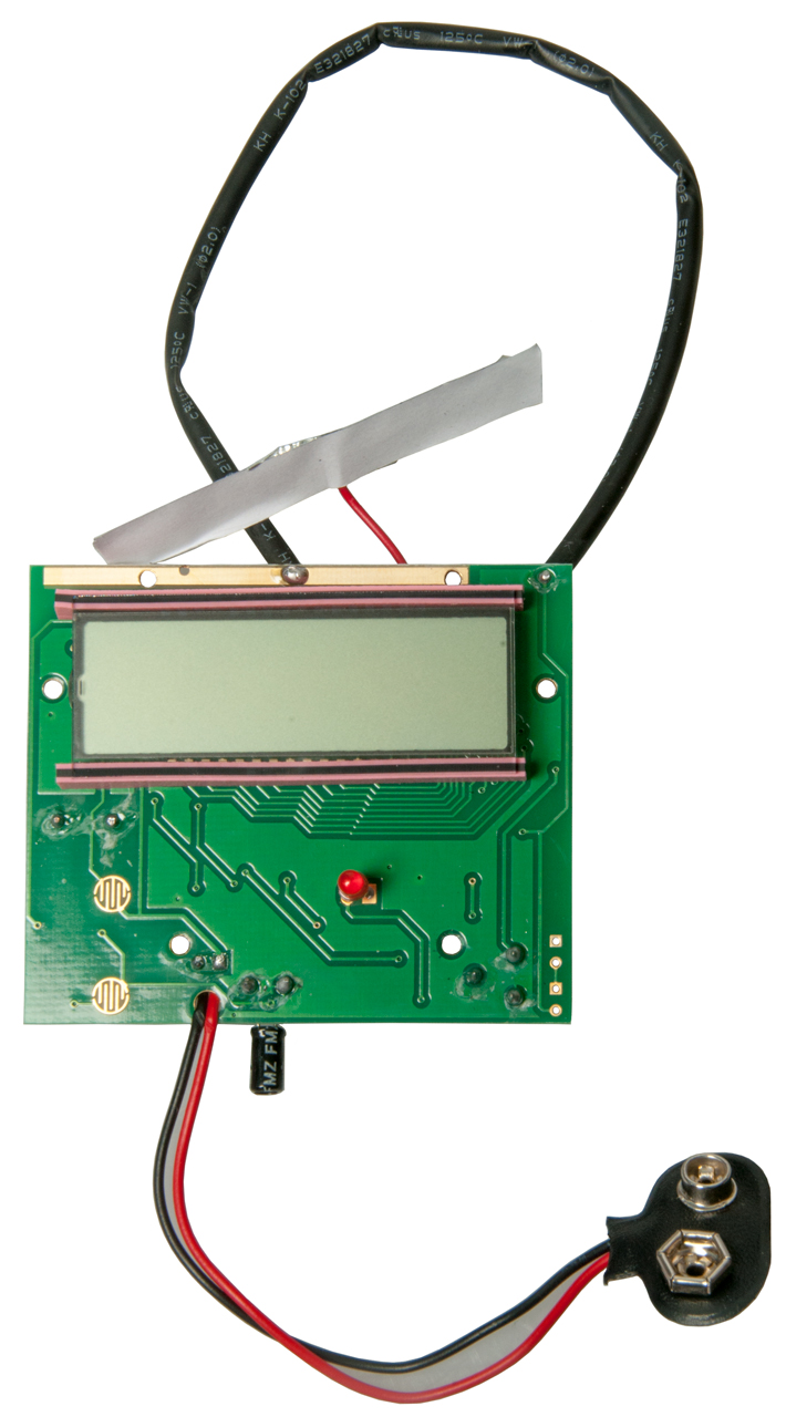
Fig 4 Circuit removed from case Front
If you link your finger you can press the Power button to turn the unit on or off.
Nothing is holding the LCD and Zebra Strip (Wiki) in place. As soon as I started probing the other side they fell off.
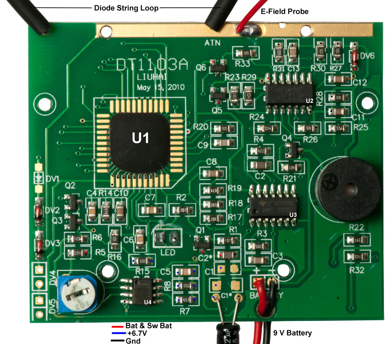
Fig 5 Circuit removed from case Back. The black shrink tubing surrounds a number of series connected diodes. It's a distributed antenna similar to the Narda units shown on this page. There's also an E-field probe
that's about the size of a stick of gum.
Fig 6 Close-up back of PCB marked DT-1103.
U1 is the LCD driver and maybe a uC?
There are markings: DV1, DV2, DV3, DV4, DV5,
Function
U1: LCD driver and maybe a uC.
U2 4013B: Dual Flip-Flop
U3 4011 Quad Nand gate
U4 8-Pin Op Amp. pin-4: gnd, pin-8 Vcc
The LM358 (Jameco) has pin out:
Pin
Function
1
Out A
2
-A In
3
+A In
4
Gnd
5
+B In
6
-B In
7
Out B
8
V+
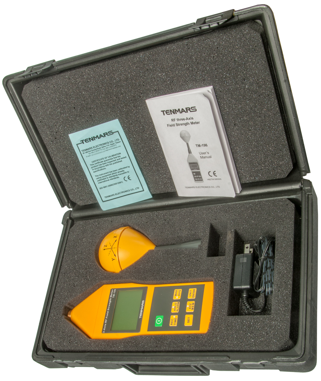
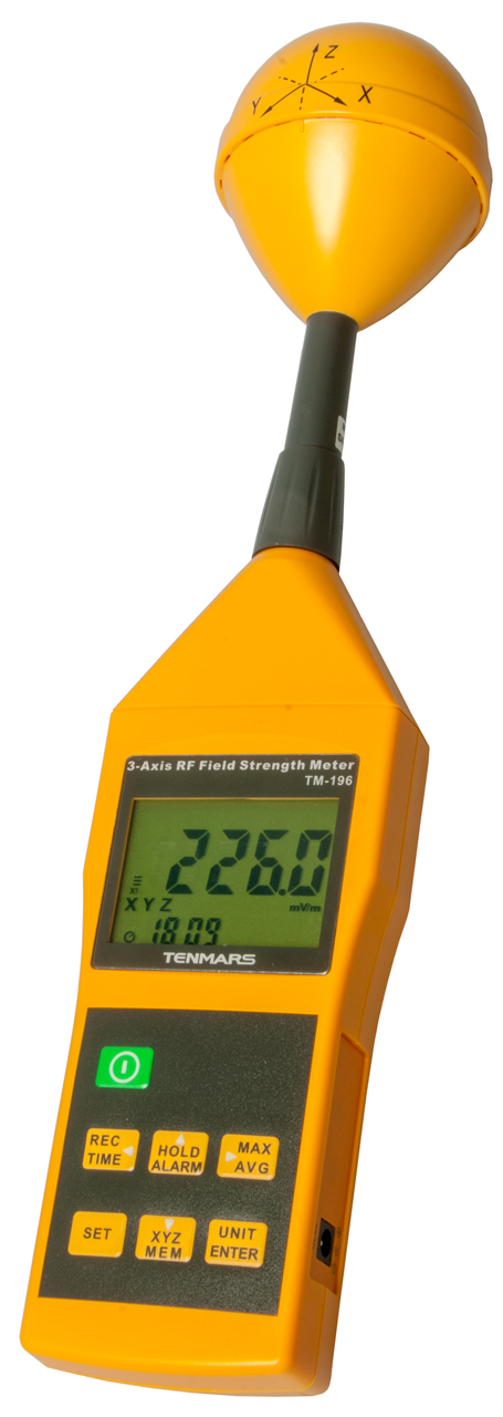
Tenmars TM-196 Three-Axis RF Field Strength Meter


The TM-196 (Tenmars) is specified to work from 10 Mhz to 8 GHz. This includes most cell phones and Wi-Fi routers.
With a measurement range of 50 mV/m to 11V/m. The accuracy is specified at 2.45 GHz as +/- 1 dB which seems very optimistic compared to the much looser accuracy specs on the Narda units.
TM-196 Photos
Fig 1
Fig 2 Empty space holds 9V battery.
Fig 3
Patents
3109988 Electromagnetic radiation monitor utilizing means responsive to all types of polarization, John C Hoover, Sperry, 1963-11-05, 343/703; 324/106; 342/351; 343/770 - multi octave frequency and multi polarization
3182262 Densiometer radiation monitoring device, Charlie O Schumann, Ramcor, 1965-05-04, 343/703; 324/96; 343/894; 324/95; 324/105; 324/443; 343/895 - uses thermistor in bridge circuit, separate antennas for: 200-225, 400-450, L, S, C & X band
3458805 Electric field meter having a pair of rotating electrodes for measuring the strength and direction of an electric field, Heinz W Kasemir, Army, 1969-07-29, - for use in weather observation like thunder storms. Wiki: Field Mill
3626290 High-frequency power measuring circuit employing two self-balancing bridges
3662260 Electric field measuring instrument with probe for sensing three orthogonal components, Aubrey M Thomas, Aubrey G Holston, Navy, 1972-05-09, - works under water
3668521 Zero temperature drift electrothermic units, Edward E Aslan, Narda Microwave,1972-06-06, 324/106; 374/E13.001; 374/E7.013; 324/95 - improved Bolometer (Wiki) [see Eppley Thermopile)
3718932 Combined multi-polarization loopstick and whip antenna, Army
3750017 Electromagnetic field measuring device, R Bowman, E Larsen, D Belsher, HHS, 1973-07-31, - "The detection and measurement of hazardous electromagnetic radiation which may pose a biological threat has become increasingly more important in view of the rapid proliferation of electronic appliances such as microwave ovens, and systems such as radio transmitters, airport radars and the like." Can use diodes or thermocouples.
3789299 Probe for radiation detector, E Aslan, Narda Microwave, 1974-01-29, 324/95; 343/703; 324/106; 343/796 - 915 & 2450 MHz uses thermocouples.
3947770 Broadband omnidirectional RF field intensity indicating device, Navy - representative of the total vertical field intensity, 2 - 32 MHz
4023093 Magnetic field radiation detector, Edward E. Aslan, Narda Microwave,
4032910 Microwave alarm, David Lipscombe Hollway, Peter Ivan Somlo, John David Hunter, Idris Gareth Morgan, CSIRO, - simple, powered by the microwave signal.
D262360 High frequency probe, Edward E. Aslan, Adeline W. Jahelka,
4365192 Isotopic broad-band survey meter, William J. Rankin, Jerome P. Whitaker, Holaday Ind, 1982-12-21, - ICs but no uC/uP. D/A drives analog meter.
4424483 Microwave radiation monitor, Edward E. Aslan, - dual Archimedean spiral with diode detector.
4431965 Microwave radiation monitor - dual Archimedean spiral with diode detector.
4588993 Broadband isotropic probe system for simultaneous measurement of complex E- and H-fields, US HHS,
4611166 Radiation hazard detector, A.N.S.I. protection guides peak sensitivity around 100 Mhz
D280388 Broadband probe, - cylinder at end of handle.
4605905 Amplifier input circuitry with compensation for pyroelectric effects, (Intersil ICL7605 & ICL7606)
4629978 Dipole antenna, - "An antenna comprising orthogonal arrays of resistive thermocouple dipoles interconnected by transversely extending conductive elements of discrete length. The components are designed to create an additional re sponse by a traveling wave effect on the dipoles along the Poynting vector to offset the fall-offin dipole sensitivity experienced as frequency rises." ...constant from 12 to 40 GHz.
4634968 Wide range radiation monitor - A.N.S.I. protection guides peak sensitivity around 100 Mhz
4647849 Two dimensional non-field perturbing, diode detected, double gapped, high sensitivity, B-dot electromagnetic field probes : 1 to 10 Ghz
4752730 Radiation monitor diode detector with constant efficiency for both CW and pulsed signals
4789869 Dipole antenna for monitoring electromagnetic waves over an extended frequency range - 0.3 to 10 MHz (low), 10 to 800 (mid), 800 to ??? (hi)
5057848 Broadband frequency meter probe, Rantec Holdings (Holaday Ind),
5266888 Wide power range radiation monitor, <5 MHz, 5 to 27 MHz, >27 MHz.
5373284 Personal VHF electromagnetic radiation monitor - belt worn, plastic tube to ear
5394164 Human-equivalent antenna for electromagnetic fields - 5 to 120 MHz
5600307 Surface charge personal electromagnetic radiation monitor and method - belt worn, plastic tube to ear
5610526 Contact hazard meter having a human equivalent circuit - Limits on contact currents to reduce the potential for RF shock and burns 1997
6084551 Electromagnetic probe for the detection of e-field and h-field radiation - 3 orthogonal coils & 3 orthogonal capacitance probes.
6154178 Ultra wideband personal electromagnetic radiation monitor : 100kHz to 1 Ghz & 300 Mhz to 100 GHz. belt worn, plastic tube to ear
10571530 Buoy array of magnetometers - detects nearby magnetic object. 452 citations! (Wiki NVC)
8223 Probe 100mw/cm2 max, 2450 Mhz patents: 3641439, 4518812, D222587, D223283, 1326243
Related
Agilent E4404B ESA-E 9kHz - 6.7 GHz Spectrum Analyzer
HP 4395A - combo box: Spectrum, Network & Impedance.
HP 8702B Lightwave Component Analyzer, Electro Optical Network Analyzer -
HP 71100A 2.9 GHz Spectrum Analyzer - really a rack mount system with amazing capabilities
ME-61 Field Strength Meter & Potomac Instruments AM, VHF TV & UHF TV Filed Intensity Meters
ML-OSA Monolight Optical Spectrum Analyzer, Beseler PM1 Darkroom Color Analyzer, Wollensak L3524D Direct Vision Spectroscope & Ocean Optics HR2000 Spectrometer
PSA-45D Avcom PSA-45D Portable TVRO Spectrum Analyzer - 950 to 2150 Mhz, i.e. the common satellite to house cable frequencies.
References
The National Institute for Occupational Safety and Health (NIOSH) - EMF -
Federal Communications Commission - OET Bulletin 56, Table 1 (pdf pg 17) has Occupational Exposure limits and General Population Exposure limits expressed as mW/cm2 with averaging times of 6 minutes or 30 minutes respectively. These are for far field measurements (Wiki). This is where the Inverse-square law (Wiki) applies.
Wiki: Electromagnetic radiation and health - Radiation Control for Health and Safety Act of 1968 - Occupational Safety and Health Act (United States) -
Nuclear Regulatory Commission - Detecting Radiation - this is about ionizing radiation, i.e. radioactivity. See Radiation Detectors.
Antenna-theory - Radiation: Do Cell Phones Present a Cancer Risk? - Specific Absorption Rate measurements -
RF Calculators to convert from V/m to other units - example the FCC OET 56 limit of 1 mw/cm2= 61.4 V/m, 1 W/m2,
YouTube: Thunderf00t:Pela: HYPER-BUSTED!! -
YouTube: Antique Wireless: Hunting Down Power Line Noise and Other RFI, 1:01:28 -
Science Based Medicine: WHO Systematic Review of RF and Cancer, Steven Novella, 2024-09-04 - Wiki: Non-ionizing radiation; Ionizing radiation
Links
PRC68, Alphanumeric Index of Web pages, Contact, Products for Sale
Page Created 2021 May 16