Telephone Power & CATV Poles
© Brooke Clarke 2012 - 2024Background
Feature Table
Photos
Hybrid Fibre-coaxial
Fire & Vegetation
Pacific Intertie DC power transmission system
Related
Links
Background
2024 Jan: New web page The End of AT&T Land Lines.
Alternating Current Mains Power
At the top is the high voltage AC. Most of the poles near my house have 12,000 Volts. At my house it's single phase (2 wires), but closer to town it's 3 phase. Three phase is required for running motors rated well above 1 horse power, industrial air conditioners, etc. May be handy for a large home shop if you want to use industrial lathes or other large consumers of power.Each house has its own transformer that steps down the 12,000 Volts to 220 VAC center tapped. The center tap has a wire to a ground rod at the base of the pole. The input to the transformer is fused. If a short develops between the transformer primary and the secondary the center tap provides a low resistance path to ground thus blowing the fuses on the transformer input. This is so that a transformer failure will not allow 12 kV AC to enter your house.
My house now has an analog meter, but I've been getting letters for a couple of years saying they will install a "smart meter" in the near future.
The entry panel to the house has two branches, one fed from each side of the pole transformer (aka: pole pig). 110 VAC circuits are fed between one branch and the center tap (neutral). 220 VAC circuits are fed from both branches.
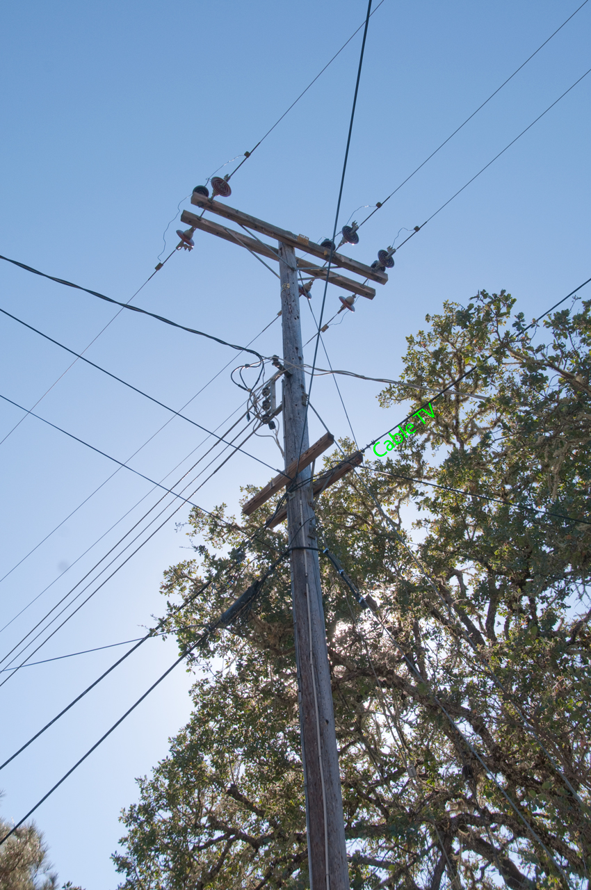
Closed Circuit Television (Cable TV)
This is a single coaxial cable that has an amplifier at regular intervals to make up for cable loss. Also there are taps, typically with four outputs to feed houses. Originally only used as a one way system to distribute analog TV. Now used with cable modems as a two way internet connection. The latest wrinkle is to deliver movies as digital data on demand, either free or pay per view. My house is too far from town so there's no cable TV here.Fiber Optic Data
This is a way to carry a very large amount of digital data. There's a FO line that terminates a few miles from my house and from there DSL is routed over the copper twisted pair line.Telephone
This is classical analog telephone or more modern Asynchronous Digital Subscriber Line (ADSL) for a two way internet connection. It uses a much wider bandwidth on the twisted pair copper lines and so can not be used with loading coils that are commonly used to supply analog voice phone service to people far from the central telephone office. There's distance limit on how far DSL can be delivered.Feature Table
HV AC Tel/DSL CATV/
Broadband
Comments
Fig 1 yes yes
Fig 2 yes yes
Fig 3 yes yes yes Fiber
Fig 4 yes
yes
Fig 5 yes yes
1ph 3wire
Fig 6 yes
60kV
Fig 7 yes yes
Fig 8 yes yes yes
Fig 9 yes yes yes BTN-M node Fig 10 yes
Fiber
Fig 11 yes yes yes DSLAM
X-box
FiberFig 12 yes
Cap bank
Fiber
Fig 13 yes yes yes BTN-M node
CATV info
Fig 14 yes yes
my pole
Fig 15 yes yes
my DSL
Fig 16
yes
my DSL
Fig 17 yes yes
my underground
Fig 18
yes
my NID
Fig 19 yes
outdoor
electric
panel
Fig 20
yes
loading coils
Fig 21 yes
69kV
power
tower
Fig 22 yes
Pwr Two
close up
Fig 23
yes
tel boxes
Fig 24
ISDN
punch-down
block inside
Fig 25
pole maint
Fig 26
pole brace
Fig 27
Fig 44
PG&E Smart Meter Repeater
New PG&E pole, old AT&T pole (D800E)
Fig 28
cut pole
new pole
Fig 29
cut pole
new pole
Fig_31
General Instrument, Jerrold Starline BTN-M Broadband Telecommunications Node Fig_32
"
Fig_33
"
Fig_34
"
Fig_35
"
Fig 36
Steel Transmission Poles on ground ready for installation
Fig 45
New Steel Transmission poles on next hill (D800E)
Fig 37
Water Pump Pole replaced, why?
Fig 38
Excavator in strange place (for 3 new transmission poles)
Fig 39
New Transmission Towers on the next ridge Fig 40
Water Pump Pole replaced Fig 41
PG&E new Voltage Regulator Nov 2021
Fig 42
2022-01-25 New Voltage Regulator in Ukiah Fig 43
Burger King (Perkins St) Hi & Lo power EV charging
Fig 43B
Tesla Super Charger
Fig 46
Woodpecker hotel & Vulture
Fig 47
Black Boxes Chained to Poles
Fig 48 & Fig49
Gift Wrapped Pole
Fig 50
Fault Indicator (3 Rapid Red flashing Lights) Fig 51
Pad Mounted Transformer
Fig 52
Helicopter N216AP lifting PG&E pole
Fig 53
Sagging Lines
Photos
Click on photo to see larger version. If your cursor is a plus sign click again for even larger version.
Fig
1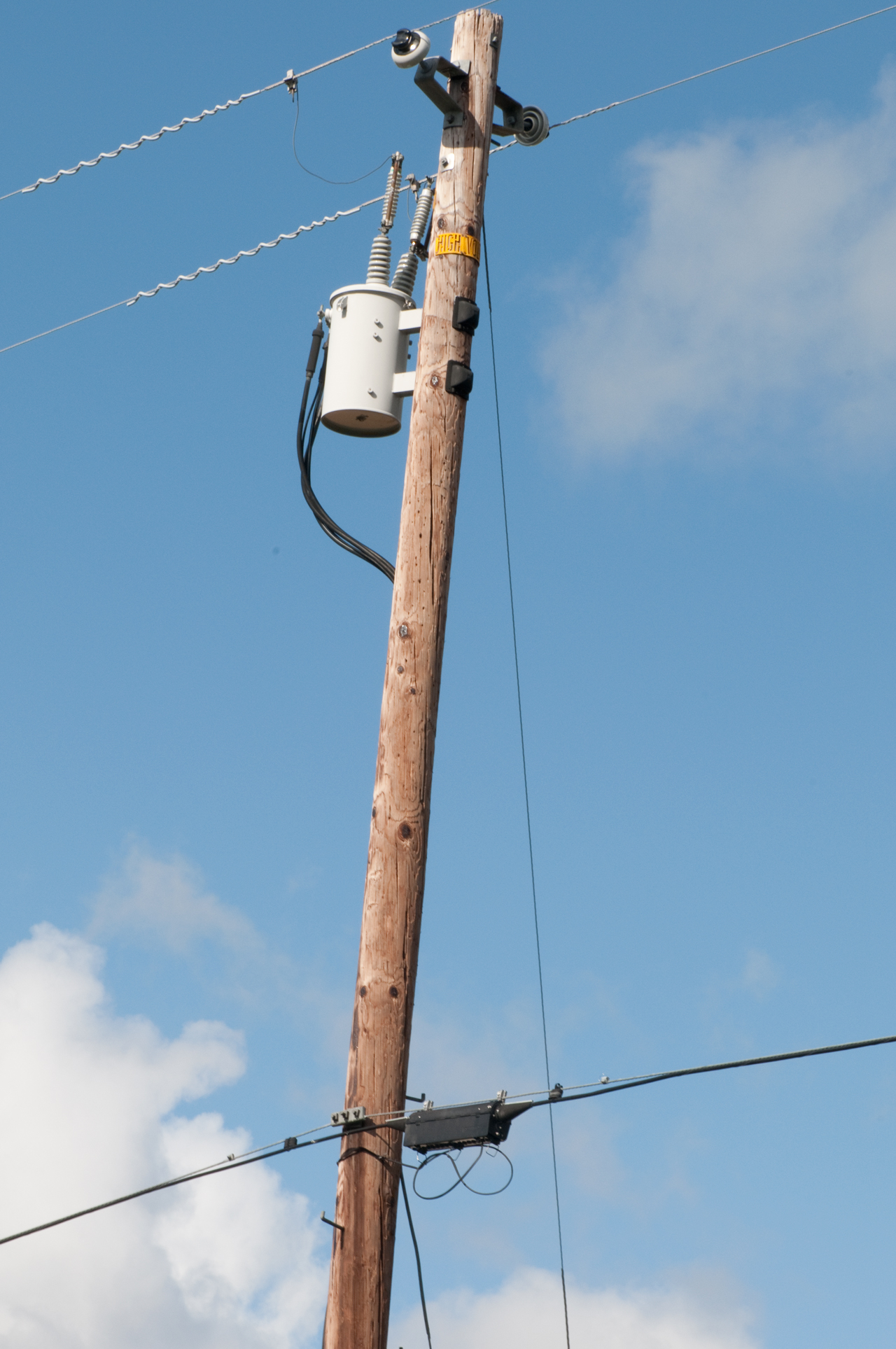 |
Single Phase 12kV AC
Mains Copper telephone (DSL) cable. |
|||||||||||||||||||||
Fig
2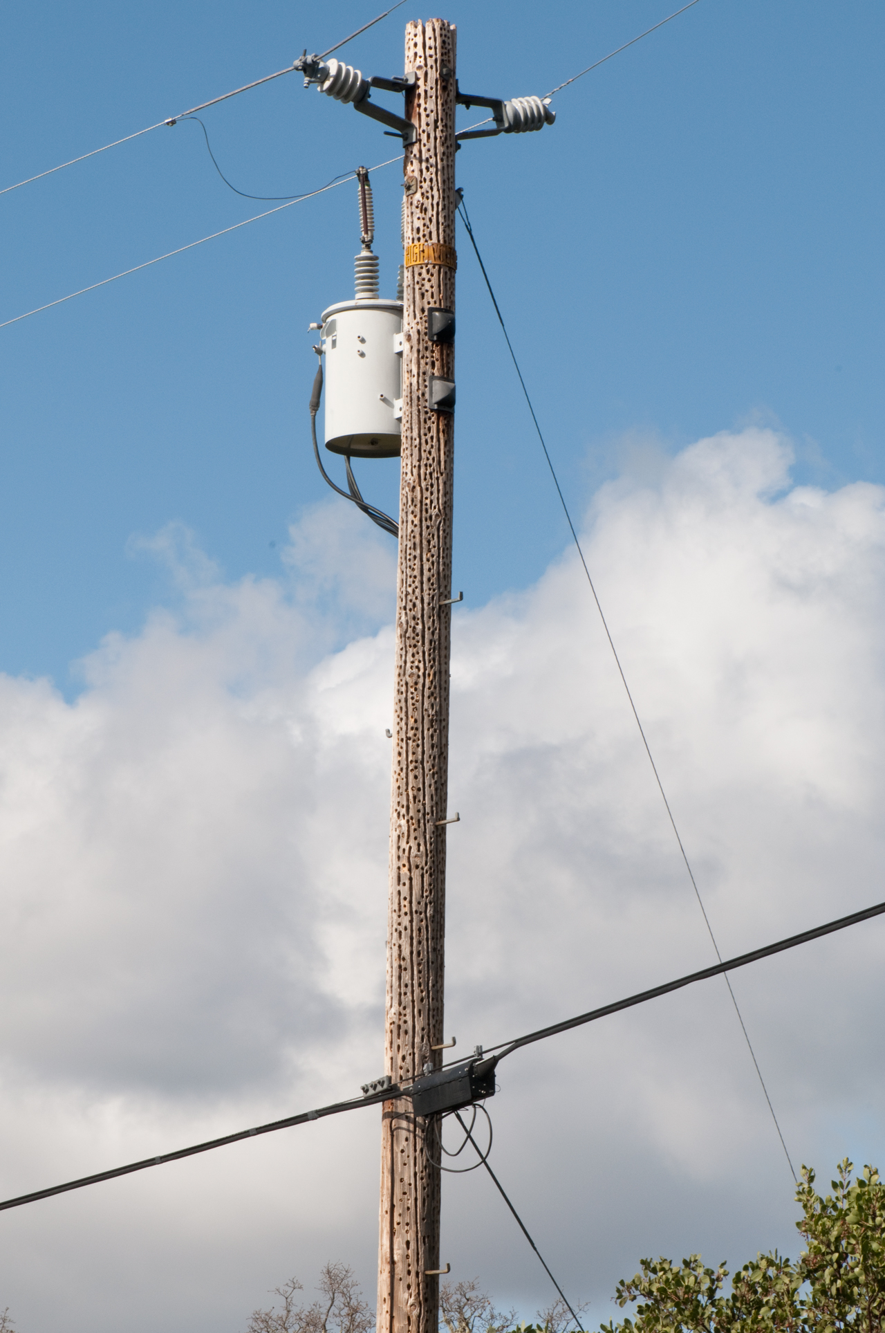 |
Single Phase 12kV AC
Mains Copper telephone (DSL) cable. |
|||||||||||||||||||||
Fig
3
|
Cable TV(fiber
only) top left making a right turn. Copper
pair telephone cable. Also see Fig 8 More photos of Cable TV
|
|||||||||||||||||||||
Fig
4 |
Single Phase 12kV AC
Mains A single petticoat insulator corresponds to about 12 kV, see Fig 22. Two phone trunk cables, one makiing a left turn and the other going straight. |
|||||||||||||||||||||
Fig
5 |
The end of the 3-phase
12 kV AC mains. There's a water well and storage tank to the right fed by the heavy black cable. The left-hand drop is a 1-ph 3-wire 120/240V supply and the right-hand one is a 4-wire high-leg delta (Wiki). (thanks to Paul C. & N. McLain) There's also a phone feed to the well house.
|
|||||||||||||||||||||
Fig 40
|
See Fig 5 above for views of this pole
prior to it's replacement. This is the only pole I've seen where the cable TV and phone lines were moved. There are many many poles around here where the new pole has the PG&E electric lines and the old pole right next to it has the cable TV and phone lines with it's top chopped off. (eg. see Fig 28) |
|||||||||||||||||||||
Fig
6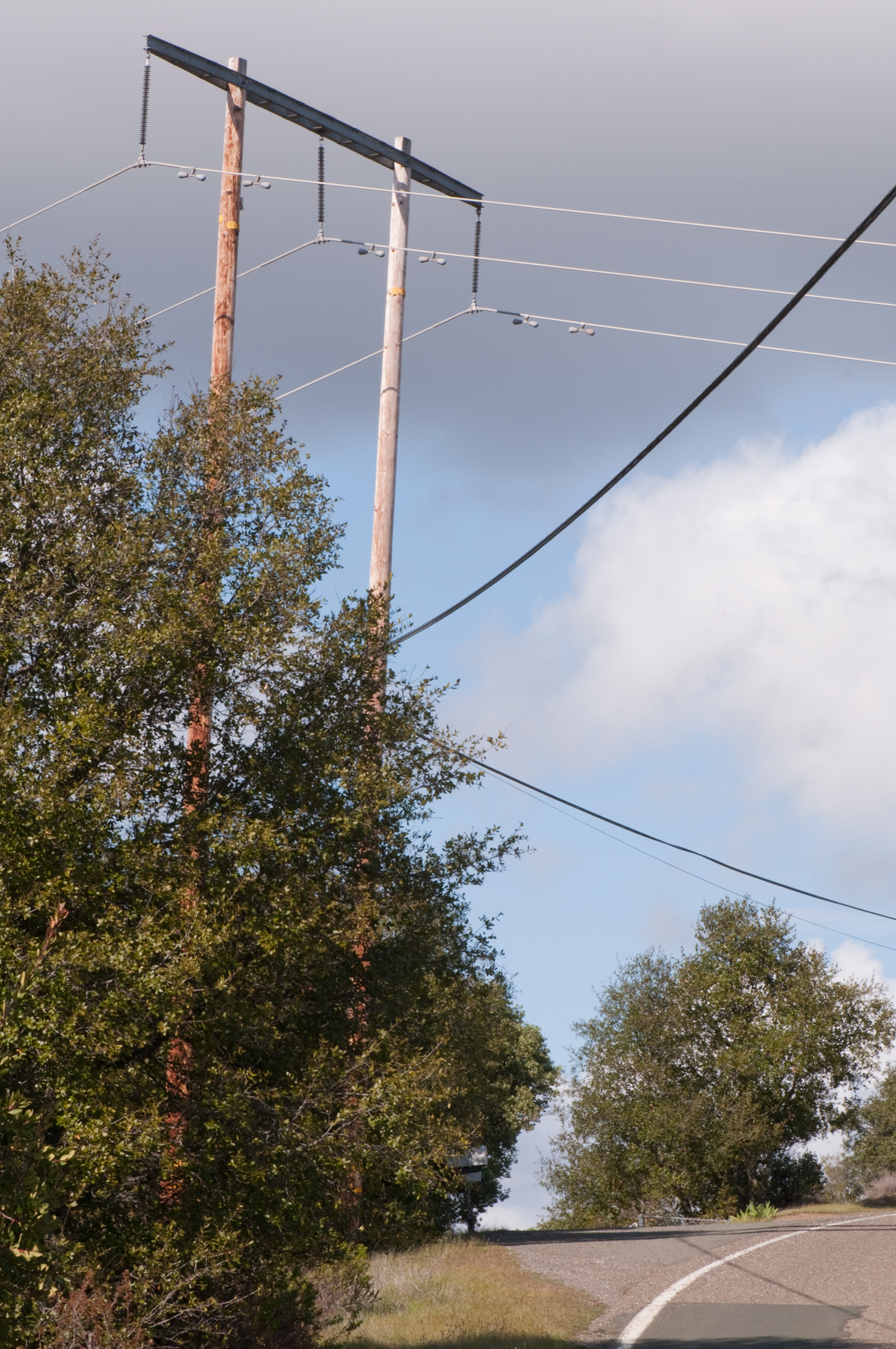 |
60 kV Transmission line
crosses the road and the 12 kV distribution line. |
|||||||||||||||||||||
Fig
7 |
3-Phase 12 kV AC Mains
with a fuse in each of the three wires. Copper telephone cable. |
|||||||||||||||||||||
Fig
8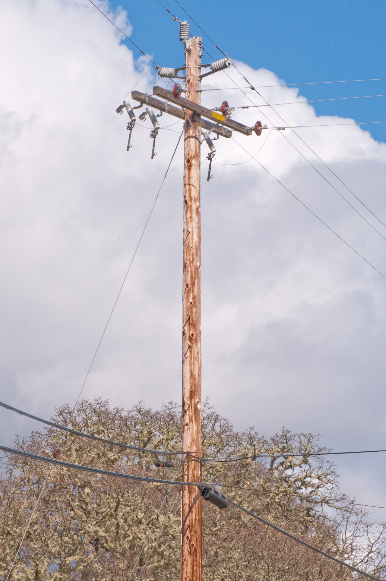 |
T intersection on the
street and on the pole. 3-Phase 12 kV AC going along the main road. The 3-phase lines to the right are not connected to the main line above because the three switches(cutouts) are open. This is the idea of a grid. Lines can be connected together in different ways. This allows isolating part of the grid while keeping the rest of the grid hot. Without the switches you would need to shut down a much larger area if there was a problem anywhere. The Comcast fiber cable makes a right turn here and does not continue on my street. The telephone cable continues up my street. |
|||||||||||||||||||||
Fig
9 |
Another T street
intersection. This time all the 3-phase 12 kV lines are connected (switches closed). 220 VAC feed from adjacent pole to a house. Cable TV coax & BTN-M node Phone cable and junction boxes. |
|||||||||||||||||||||
Fig
10 |
3-Phase 12 kV AC near
the DSL box. U-turn is on fiber cable to avoid cutting it. thanks to David WB8FOZ: aka:"snowshoe" a) So there's enough slack to allow both ends to the ground & into the splice truck. b) If a pole is wiped out, the snowshoe breaks loose before the fiber is overstressed and fractures internally. |
|||||||||||||||||||||
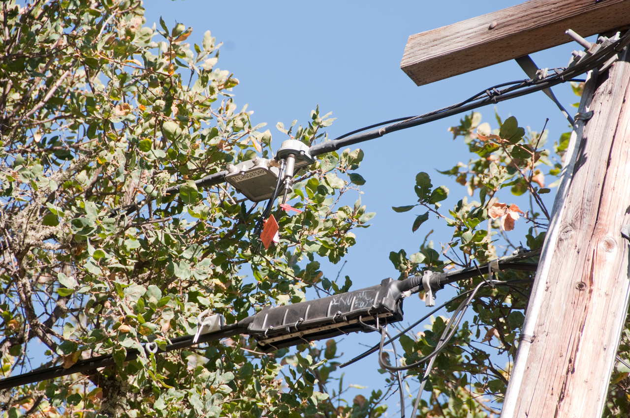
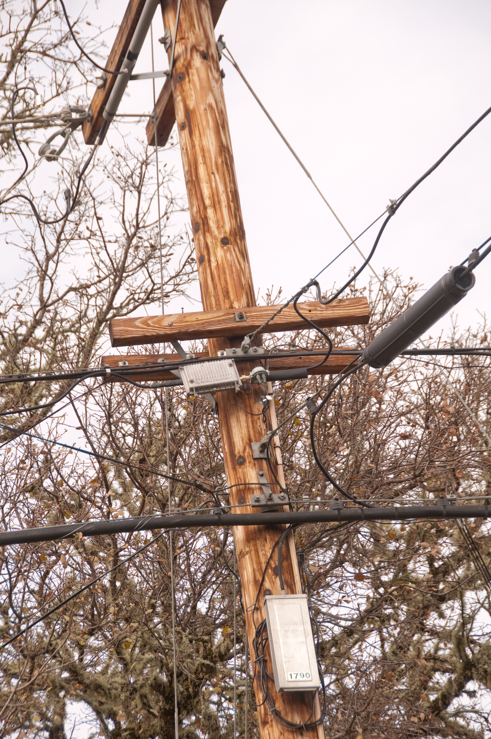
Fig
11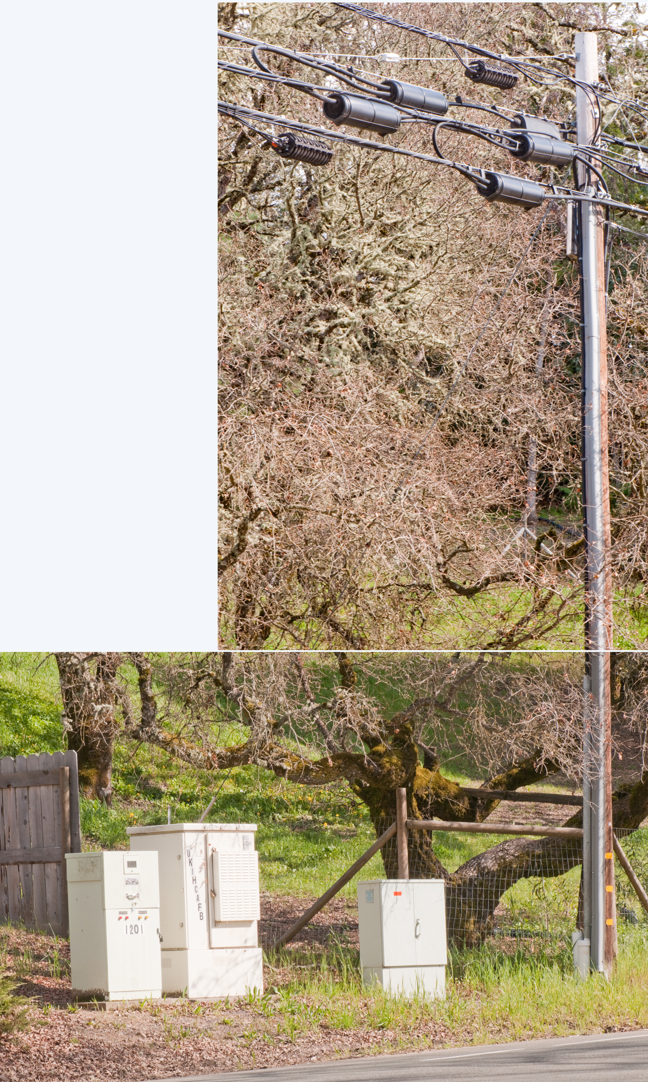 Note cross-connect boxes (on right) can appear by themselves, But DSLAM cabinets (center) will always be accompanied by power cabinets (left). |
There's a fiber optic
cable from the central telephone office that feeds a
box with a DSL converter. There's also cable TV on the pole. Digital subscriber line access multiplexer (Wiki: DSLAM) Note: the maximum distance from the DSLAM to subscriber is about 17,000 feet. Power box is on left with labels and lights about mains power and generator. The DSLAM box is in the center. Crossover box is the one on the right.  |
|||||||||||||||||||||
| DLSAM box -
DMAX1120 (Google)
(top to bottom) Battery (12 hour) cross-connect Primary Shelf cross-connect Expansion Shelf 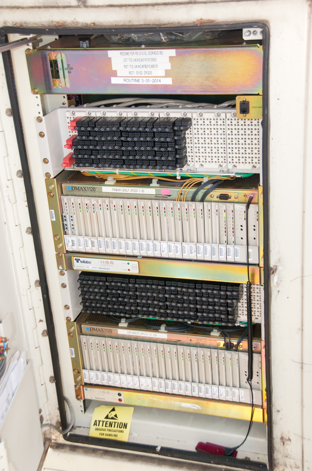 |
Crossover box shown below. Note
large punch down areas on left and right. Each
of these is connected to a cable with a large number
of pairs. These connections are not
disturbed. In the center part are the crossover
pairs that connect one cable to the other cable.
If a pair has a problem in cable A then that pair can
be abandoned and the crossover connected to a good
pair. But when there are no longer any good
pairs there's a problem and a new cable needs to be
installed.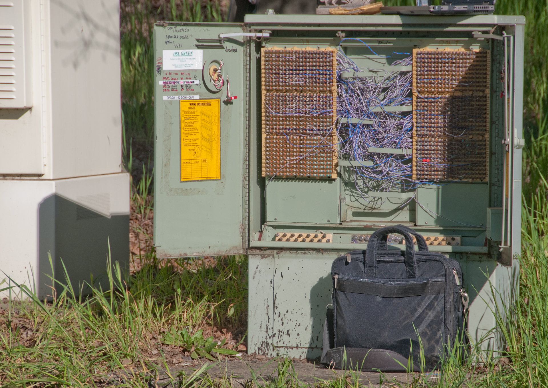 While I was at the DSLAM there were two other subscribers, both of which could receive telephone calls, but had no dial tone so could not place outgoing calls. Above the two rows of line cards are black devices with a white circle. These are Lightening protectors. 84 in the upper group and 132 in the lower group for a total of 216. DSLAM box cards at the left with: 2 LEDs are for Plain Old Telephone Service (POTS). 3 LEDs are for ADSL. 4 LEDs are for Optical Cable Transceivers (OC3-XCVR). 8 LEDs are Central Processing Units (CPU). 3 LEDs & 3 Test Points are Power Supply Units (PSU). 4 LEDs & 2 Pair of jacks are ?? When a black cross-connect block is pulled the subscriber is disconnected and a test set can be used to check for dial tone and place a test call. PS It's my understanding that the line cards could be replaced with a Fiber To The Home (FTTH) line card. But that would require running fiber from the DSLAM to each house. also see my web page The End of AT&T Landline Telephones. |
|||||||||||||||||||||
Backup
Generator to maintain DSL
during PG&E outages.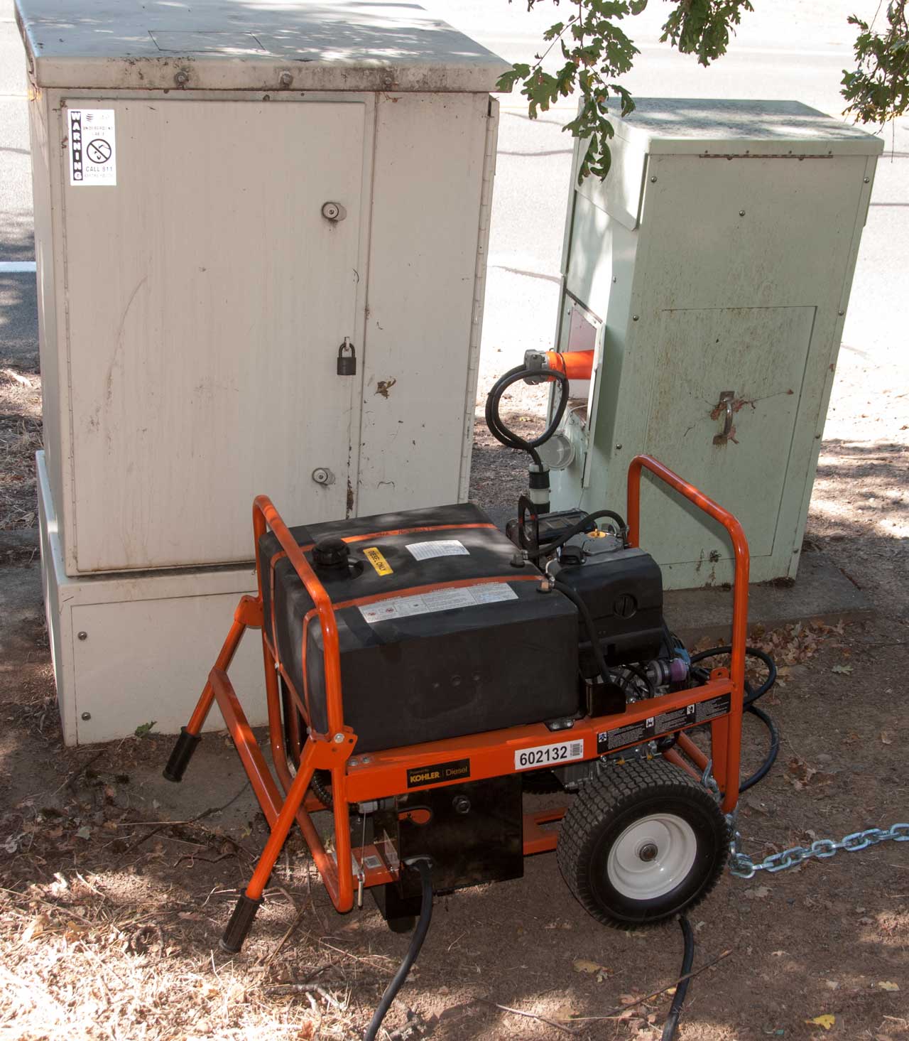 |
DSL is provisioned on top of a normal
copper pair phone line. The phone line falls
under FCC Title II regulations, so there's a
requirement that it work during emergency situations
such as AC power failure. This is not the case
for most other providers of internet service. Also see Rural Internet, Generators, at&t DSL, This is a specialized Kohler Diesel generator. It has a very large fuel tank and a small engine generator. It might be the Genrac XD5000E "Shore Power" (Wiki) generator. 12 Gallon fuel tank gives run time of 32.5 hours at 50% load (505 of 5000 Watts = 2500 Watts). But the actual load in this case is probably more like 500 Watts. 3600 RPM |
|||||||||||||||||||||
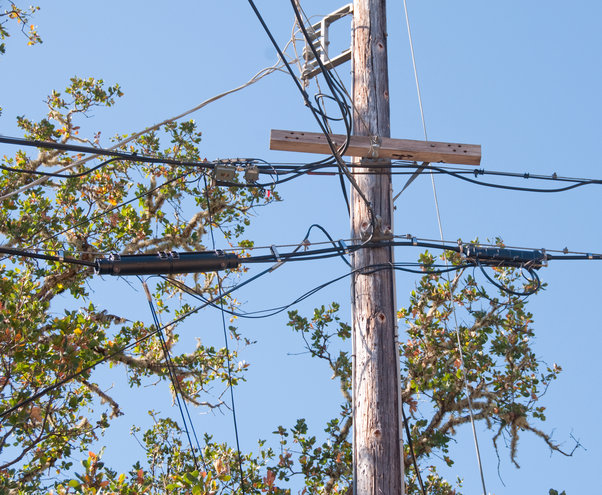
Fig
12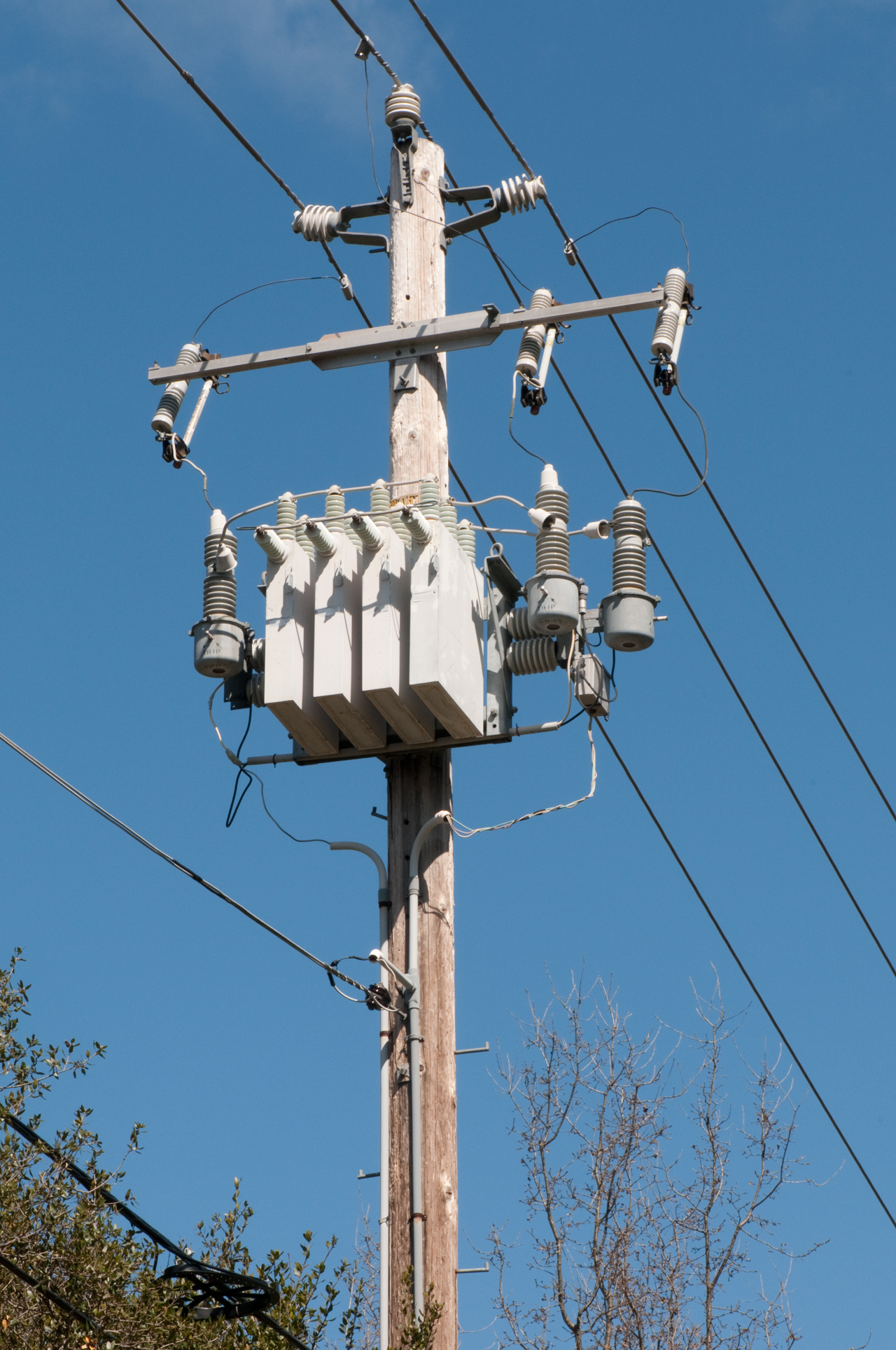 |
I think this is a capacitor bank used for
Power Factor (Wiki)
correction. Many of the loads connected to the
AC mains have inductive reactance which increases the
current in the transmission lines which is lost power
due to heat. So, by making the load look more
like a resistor less power is wasted in heating the
transmission line. In the EU there are rules about the power factor of electrical devices so that the overall system operates near a power factor of 1.0. |
|||||||||||||||||||||
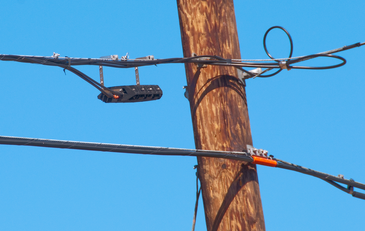
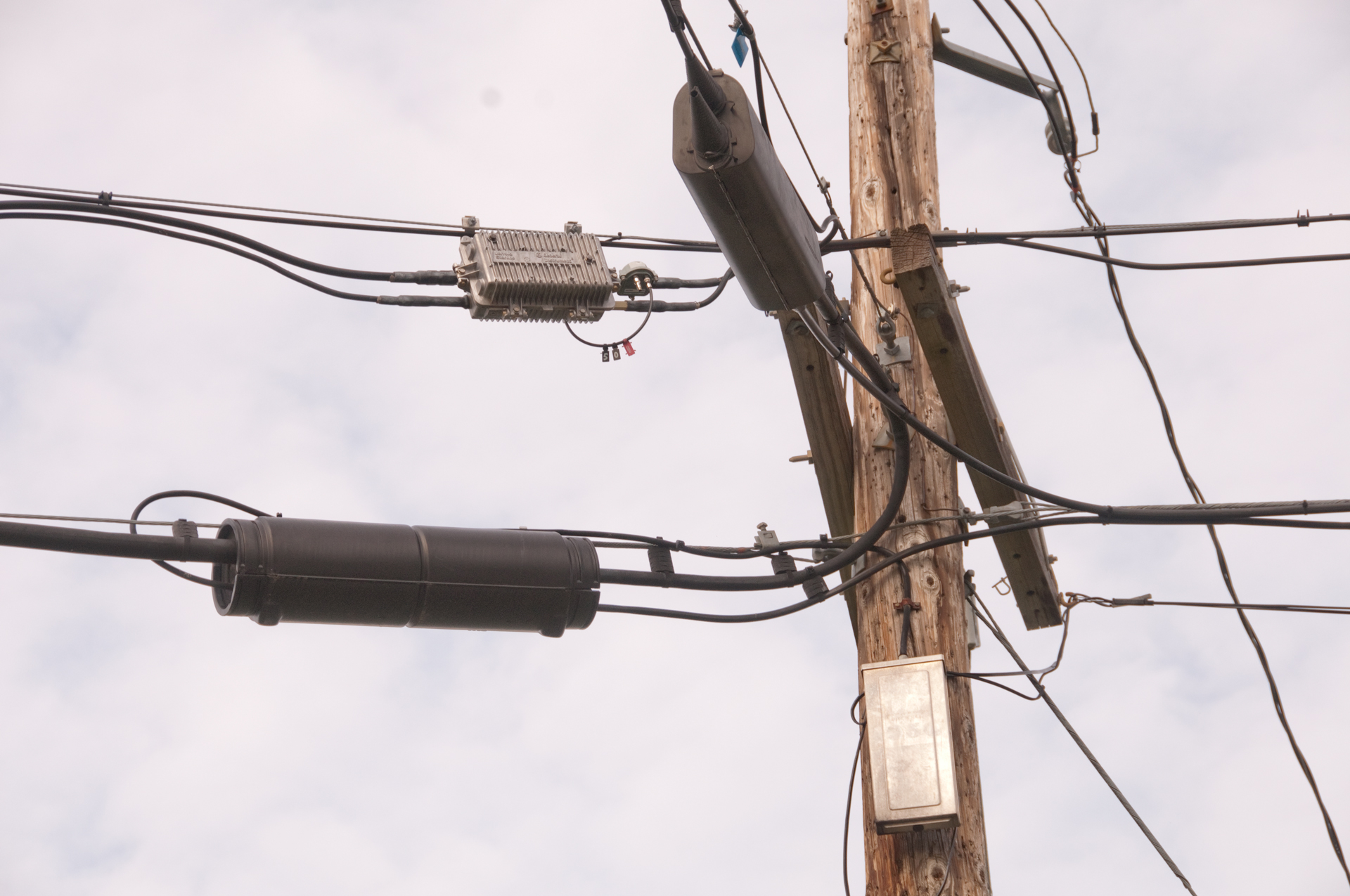
Fig
13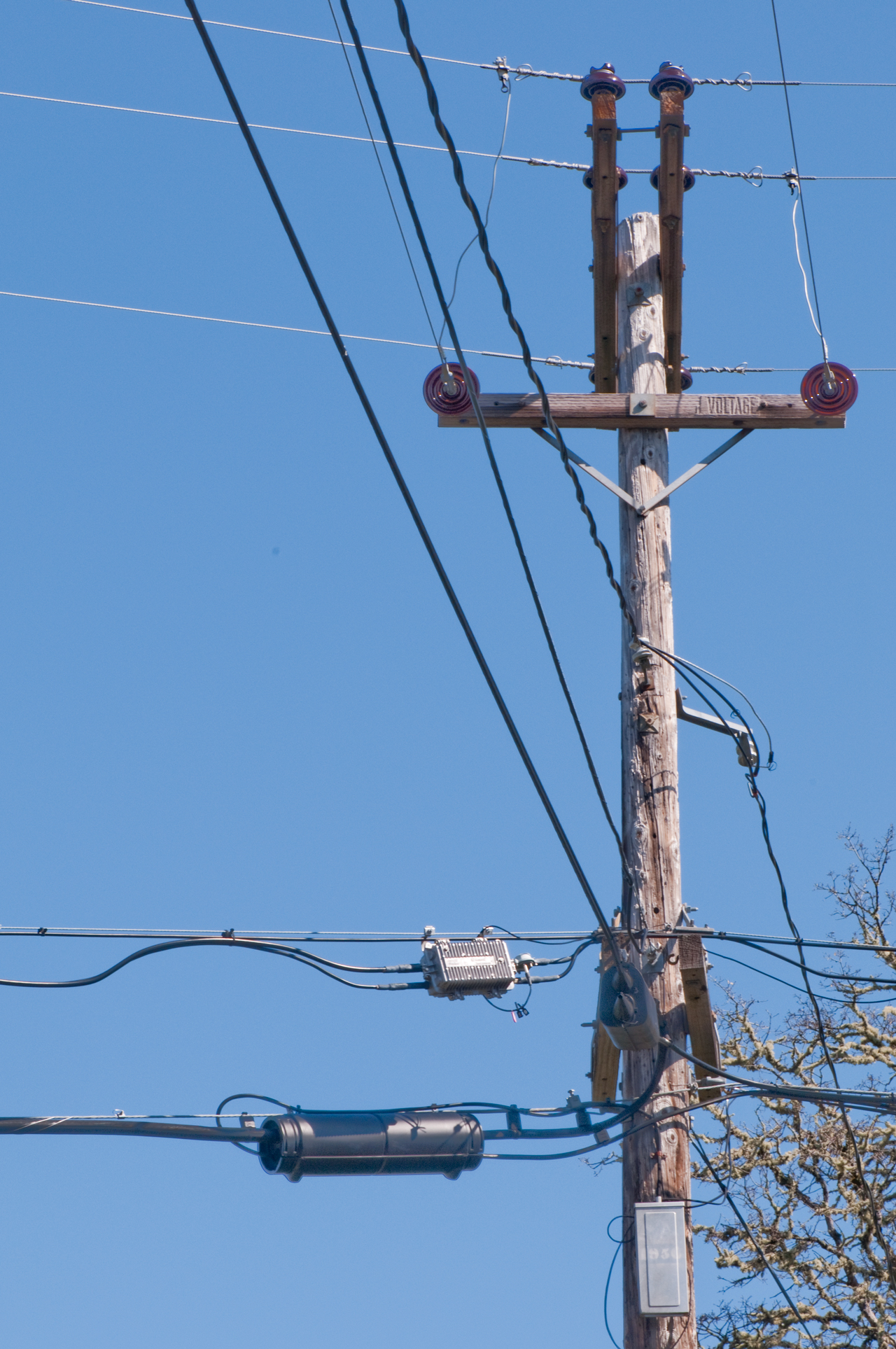 |
There is a cable TV amplifier that has 2 cables on each end, why? answer from Neal: ----------------- Because cable TV networks utilize two types of distribution cables: - TRUNK is designed for to carry signals over long distances with minimum noise and distortion. Trunk signal levels are optimized for minimum noise and distortion. Trunks may be cascaded to depths up to 30 amplifiers (although I once heard of a trunk line 67 amplifiers deep). Trunk lines are never tapped. Trunk is typically implemented with 0.750" solid aluminum sheath cable, although other sizes will work just as well. - FEEDER is designed for short runs within a small area (a block or two) to feed customers. Feeder lines are tapped as needed by neighboring structures, typically one tap per pole. Feeders run at substantially higher levels than trunk in order to provide the necessary level to drive the taps. However, the higher operating levels result in higher distortion levels; consequently, feeders are typically limited to two amplifiers ("line extenders") per run. Feeder is typically implemented with 0.500" solid aluminum sheath cable, although other sizes will work just as well. The amplifier shown in the photo is a "terminating bridger" (or a "5-amp" in the lingo of line techs, who refer to amps by their Jerrold model numbers). The trunk line enters upper left, and is amplified to a level of around +45 dBmV (which equals about -3.75 dBm, or 177.83 mV RMS at 75 ohms characteristic impedance). This signal is split three ways, producing three feeder outputs. These are the other three cables connected to the amplifiers. One feeder heads to the left to feed a neighborhood off camera. The other two head to the right to feed two more neighborhoods. For a detailed explanation, see: http://people.seas.harvard.edu/~jones/cscie129/nu_lectures/lecture13/pdf/CATV.pdf -------------------------- Also on the right there is a tap with a single coax line going to a residence. A black cylindrical telephone breakout box and a rectangular metal telephone box on the pole. |
|||||||||||||||||||||
Fig
14 |
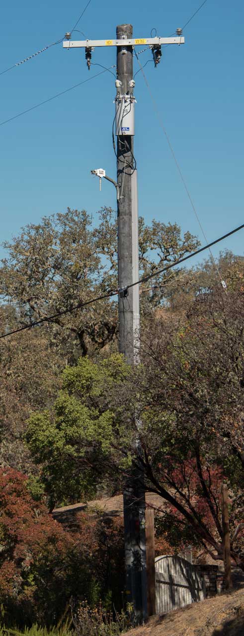
This is the pole for my
house. 6 kV single phase AC at the top with a transformer feeding center tapped 220 VAC to the house. The telephone trunk has no tap on this pole, it's on the next pole further from the central office with a a couple of return cables. This really hurts for DSL since I'm the last house that can get DSL service. |
|||||||||||||||||||||
Fig
15 |
Close up of my
telephone service at the pole. |
|||||||||||||||||||||
Fig
16 |
This is on the next
pole down the street where my two phone cables are
branched off the main telephone cable. You can see the two cables going to the right to my place. |
|||||||||||||||||||||
Fig
17 |
This is the pole for my
house. The large conduit at the left is the underground 220 VAC feed to my house. There are two telephone cables to my house. The original cable is the one that is buried in the ground. The small conduit on the right was installed when the house was built to make installing cable TV easier, but there's no way the cable TV company will extend service to those of us who are too far out in the forest so it's being used for a 6-pair phone cable. |
|||||||||||||||||||||
Fig
18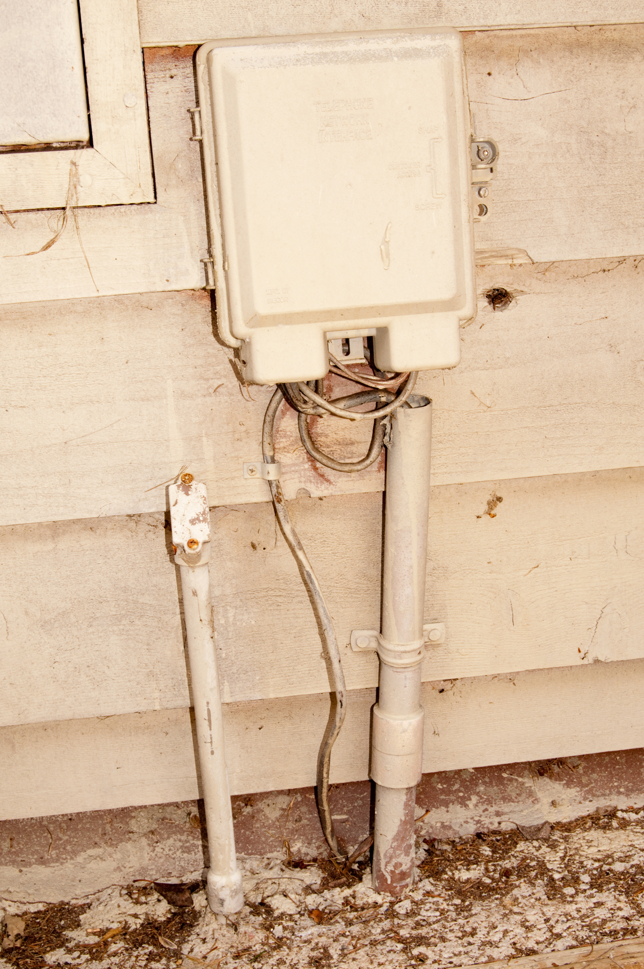 |
At the upper left of
the photo is the electric panel that also has the
electric meter. The box to it's right is the demarcation box (demark) or Network Interface Device (Wiki: NID) The cable at the bottom center is the original telephone cable. To it's right is what was supposed to be the cable TV conduit which now has another 6pair telephone cable. The small conduit to the left is the extension cord for the shipping container. 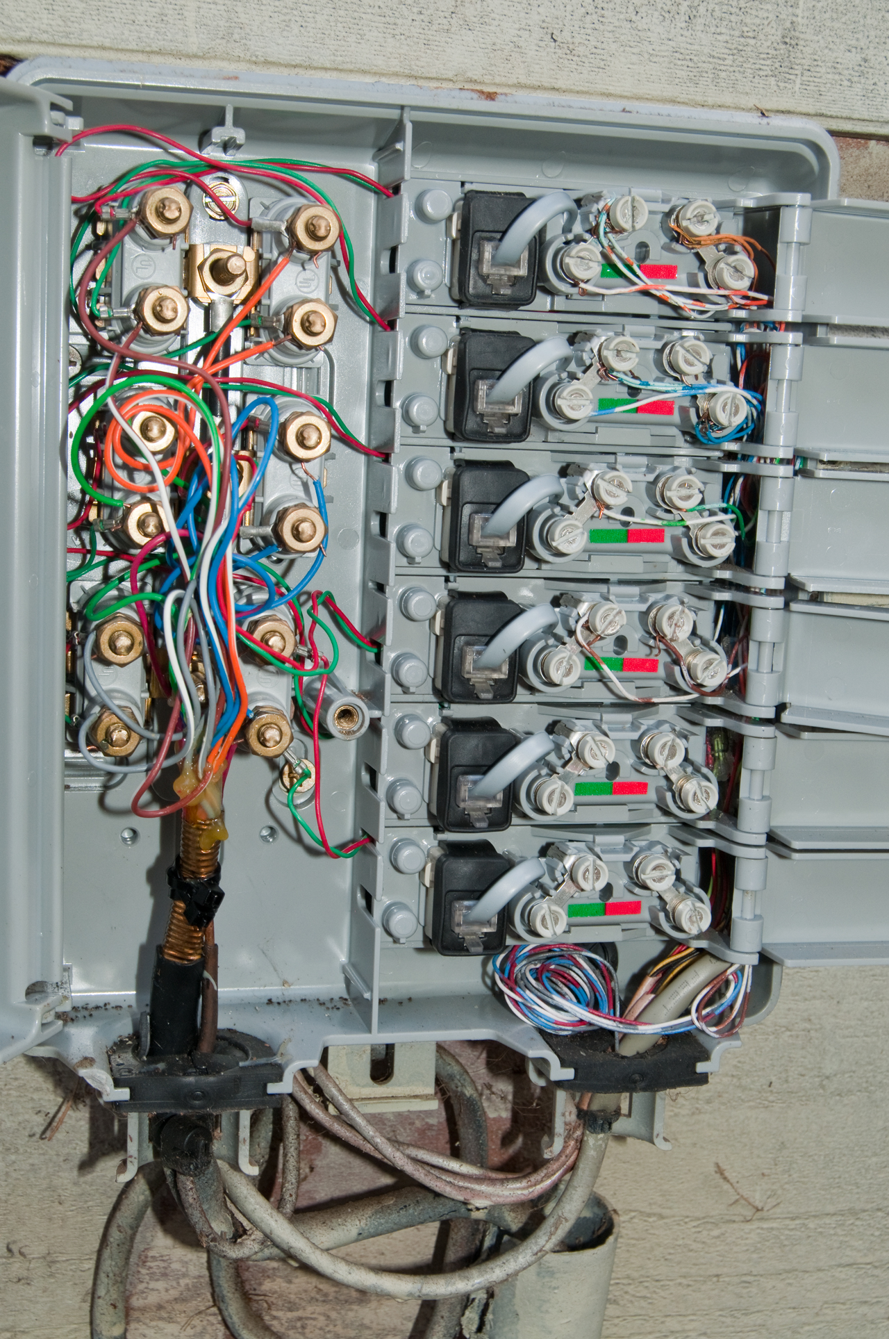 This is a 6 line demark box that came with the house. But the cover was broken. Note that each of the 6 lines has 2 pair so there's a total of 12 pairs going into the house.. CO Cable Color Code
|
|||||||||||||||||||||
Fig 23 |
 The cable in the large cable TV conduit is a 6 pair CO phone cable. The other large cable coming up from the concrete is the original CO phone cable and has been cut off, i.e. no longer being used but probably OK. The medium sized cable coming out of the wall at the lower left is a 6 pair CAT3 cable installed for ISDN service and makes a home run to the ISDN jack in my office (now used for FAX/DSL). The upper left wht/org pair is the home phone line. The upper right Blue/White pair is the FAX, DSL line. Of the group of 4 cables coming out of the wall 3 are quad cables (Red/Green & Yellow/Black) and 1 of them is the ground wire (connects at the top center of the box). Although this box can support 4 lines there are jumpers so now it's only supporting 2 lines. I'll change this in the near future when the Panasonic KX-TA824 telephone system is installed. |
|||||||||||||||||||||
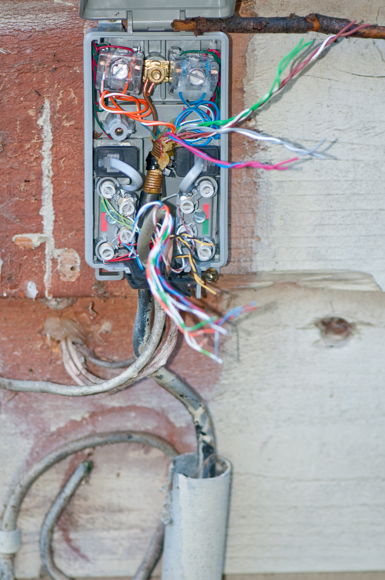
Fig 24 |
Inside end of ISDN (Wiki)
cable, maybe 1999? Wires have been brought out from the adjacent flush wall jack box and fed to this surface mount RJ-11 Jack. There are 16 punch down terminals, but they are paired so it's only 8 terminals. The Red-Green pair to the socket connects to the Wht/Brn pair from the adjacent flush box. They are in the lower left corner. Not line pair is connected to the Yellow-Black socket wires. |
|||||||||||||||||||||
Fig
19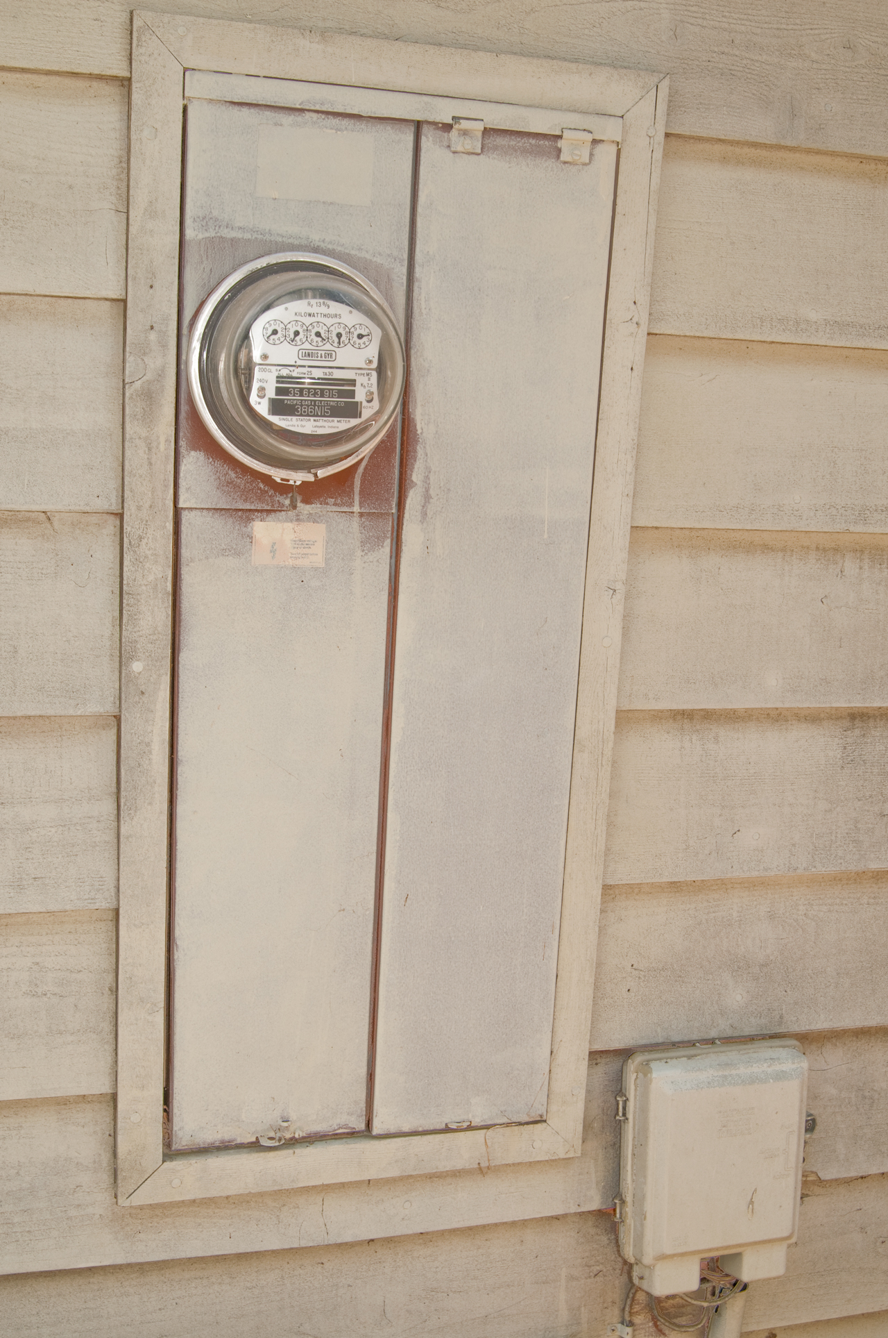 |
The left side of the AC
mains entrance panel has the underground conduit
feeding the analog electric meter. The right side contains some breakers. The door is hinged at the top and will not stay open unless someone holds it. There's another breaker panel in the garage (see the kitchen oven repair "Wiring for new oven" for a little more on it) |
|||||||||||||||||||||
Fig
20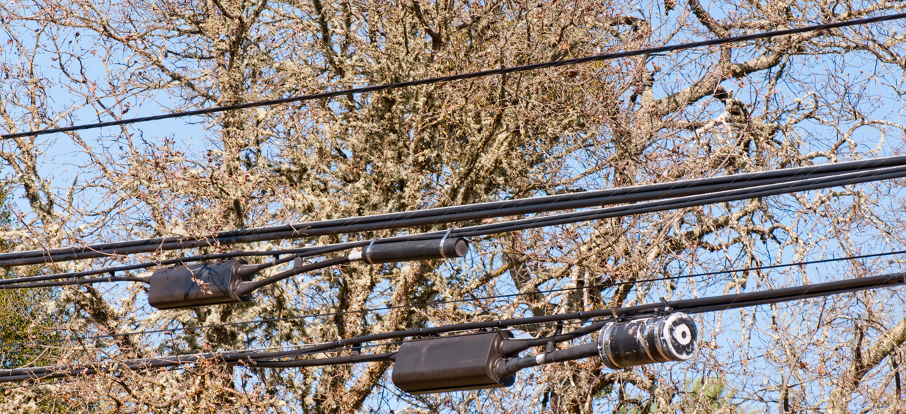 |
Small & Large
Loading Coils in the cylindrical cases. These are typically 88 mH Inductors. |
|||||||||||||||||||||
Fig
21 |
This high voltage power
tower is visible from my front door. See close up view (Fig 21) below. |
|||||||||||||||||||||
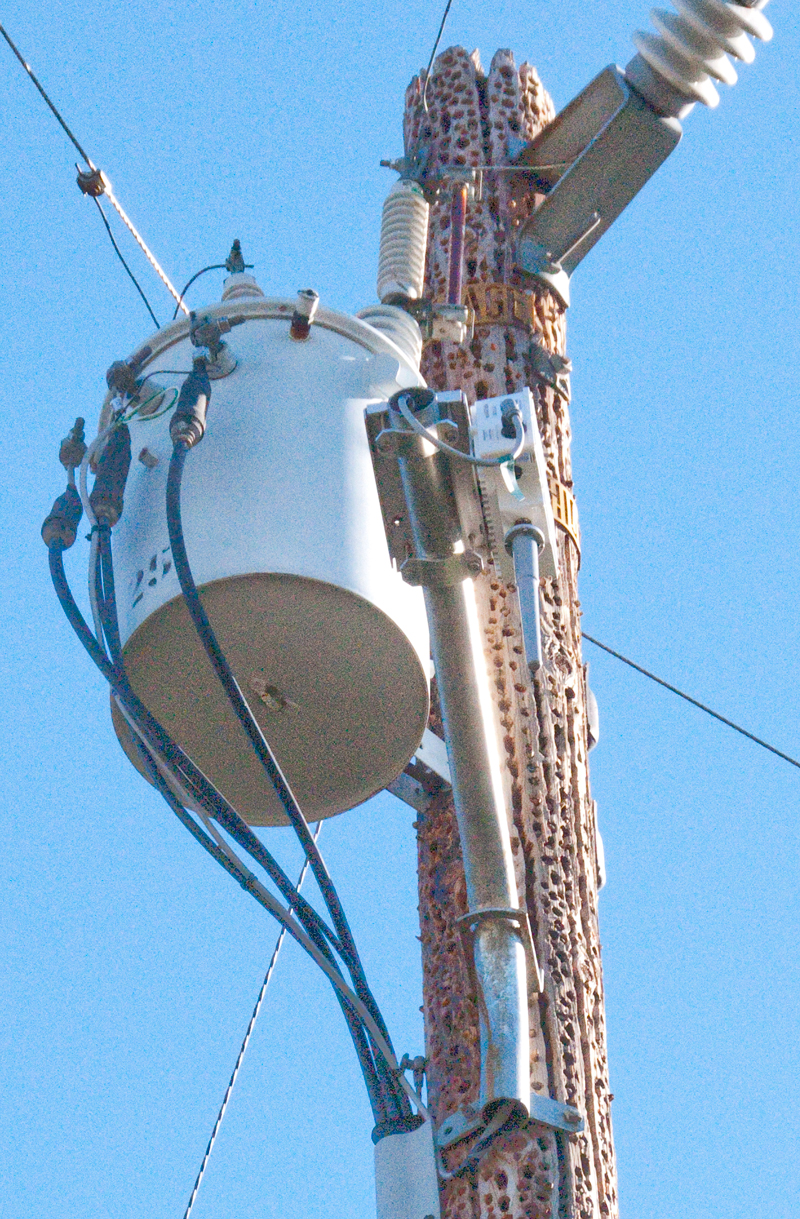
Fig
22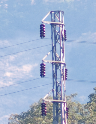 |
Close up of High
Voltage Transmission Tower. 6 Wires or two three
phase lines. Distribution (Wiki) is what's on the wooden poles and is commonly 7.2, 12.47, 25, and 34.5 kV, "12 kV for the poles on my street. Transmission (Wiki) is for moving electricity over long distances and is done at voltages much higher than for distribution and the height above ground is also much higher. You can estimate the line-line voltage by counting the petticoat insulators: 1 - 12 Kv 3 - 34.5kv 4 - 46kv 5 - 69kv 7 - 92kv 22 -345kv So for this case 5 petticoats = 69 kV line to line voltage or (69 kV/SQRT(3) = 39.8 kV to ground. PS to take this photo from my front door requires a long telephoto lens ( and scroll down a little). |
|||||||||||||||||||||
Fig 25 Pole
Maintenance
|
Man on right (00:00:12) with chain saw
or weed eater. Man on left (00:26:00) working at base of pole. Osmose - Wood Preservation - Wood Pole Maintenance - |
|||||||||||||||||||||
Fig 26 Pole Brace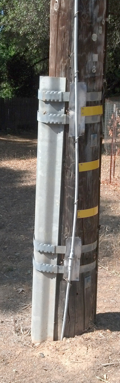 |
||||||||||||||||||||||
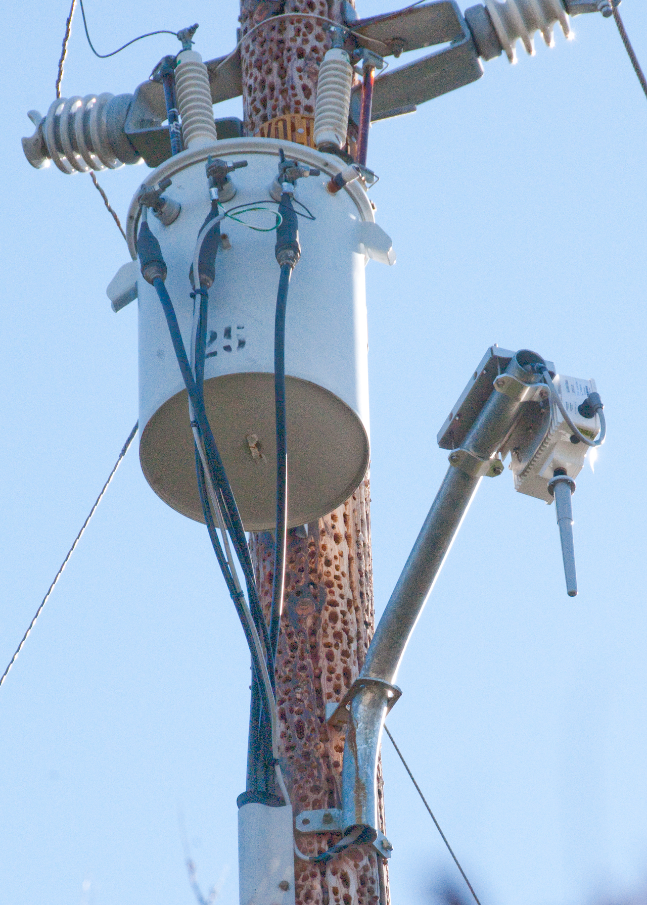
Fig 27 PG&G Smart Meter Repeater
|
Over a year ago PG&E installed a
smart electric meter but it was read the old fashioned
way. But now Jan 2015, a repeater has been installed on a ridge line up the road and it's now "smart". Note since this is a PG&E pole they just use the neutral and one of the 115 VAC transformer outputs to power the repeater. If the power fails at that pole, like happened last week, PG&E can see that the repeater is down since it has an ID. They can also see what houses up stream have power and figure out about where the problem is. PG&E replaced the pole that had been used by every woodpecker in the neighborhood, including the Smart Meter repeater. They cut off the top of the old pole just above the phone lines which are still on the old pole. This has been done to maybe a hundred nearby poles in the last year. |
|||||||||||||||||||||
Fig 28 at&t no
longer maintaining poles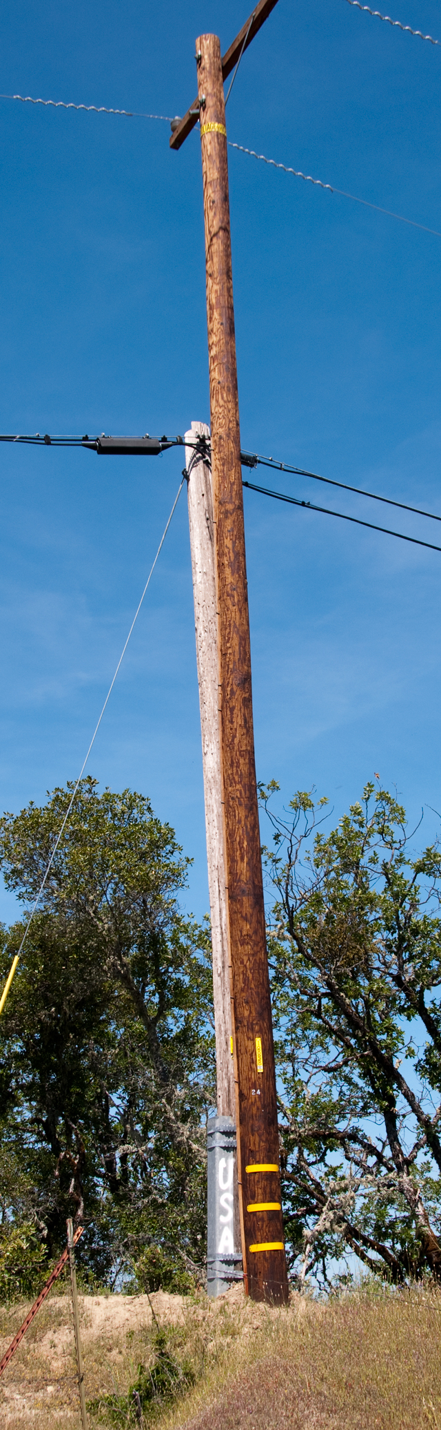 |
PG&E has put in a new pole and
moved their wires to the new pole then cut off the top
of the old pole leaving the at&t phone
cable. But at&t has not moved the phone
cable to the new pole. It's my understanding
that at&t has an obligation to maintain the
outside copper wires, but it seems they are not doing
it. These two poles are on my street. I wonder in how many other places are they ignoring maintenance with the idea that they are going to abandon this outside plant? California AB 2395 "Telecommunications: replacement of public switched telephone network." |
|||||||||||||||||||||
Fig 29 at&t no
longer maintaining poles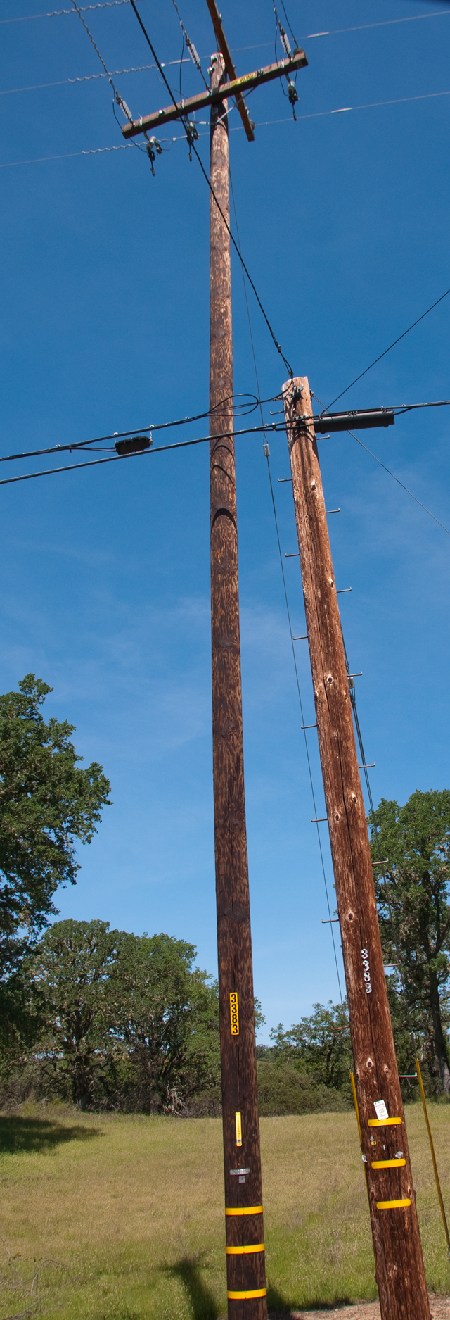 |
PG&E has put in a new pole and moved their wires to the new pole then cut off the top of the old pole leaving the at&t phone cable. But at&t has not moved the phone cable to the new pole. It's my understanding that at&t has an obligation to maintain the outside copper wires, but it seems they are not doing it. | |||||||||||||||||||||
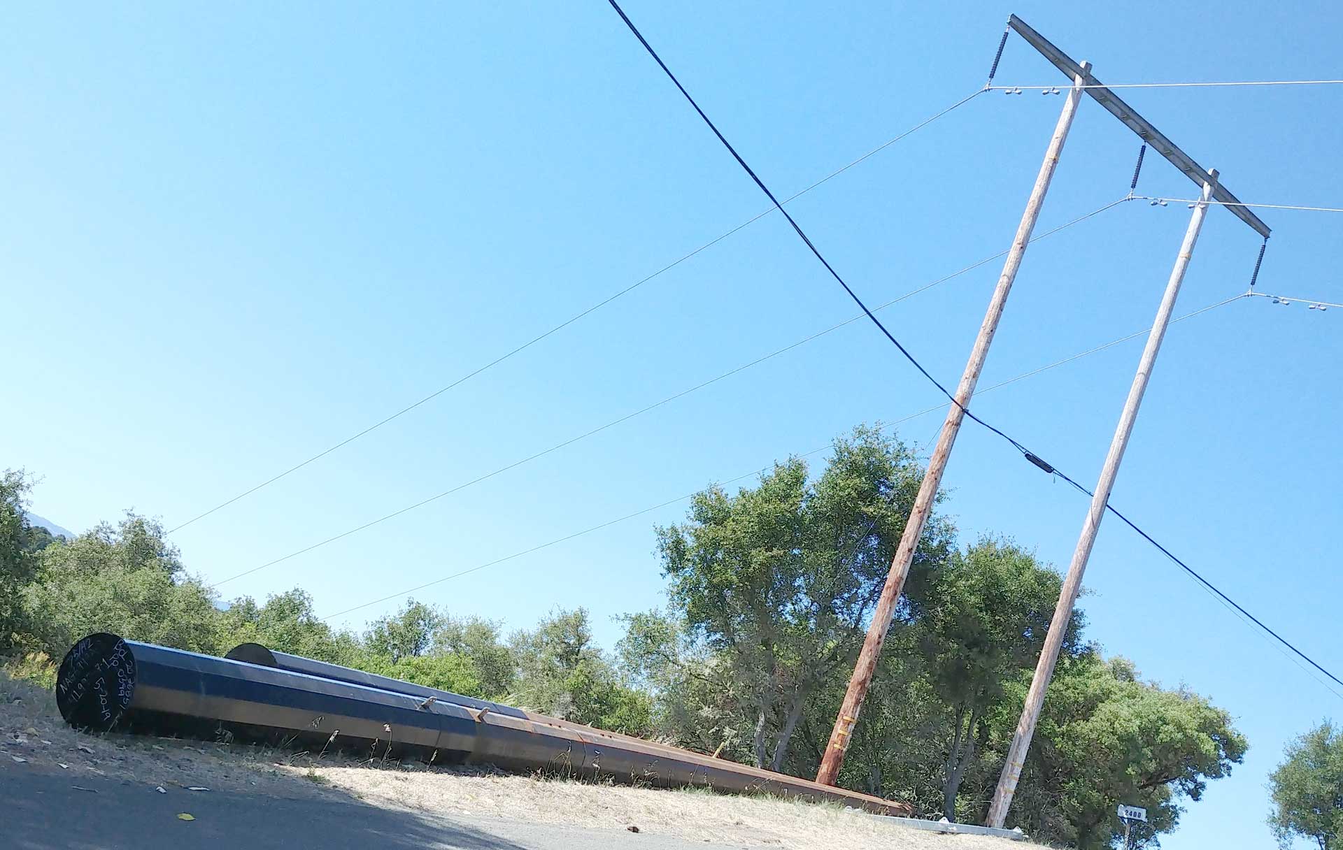
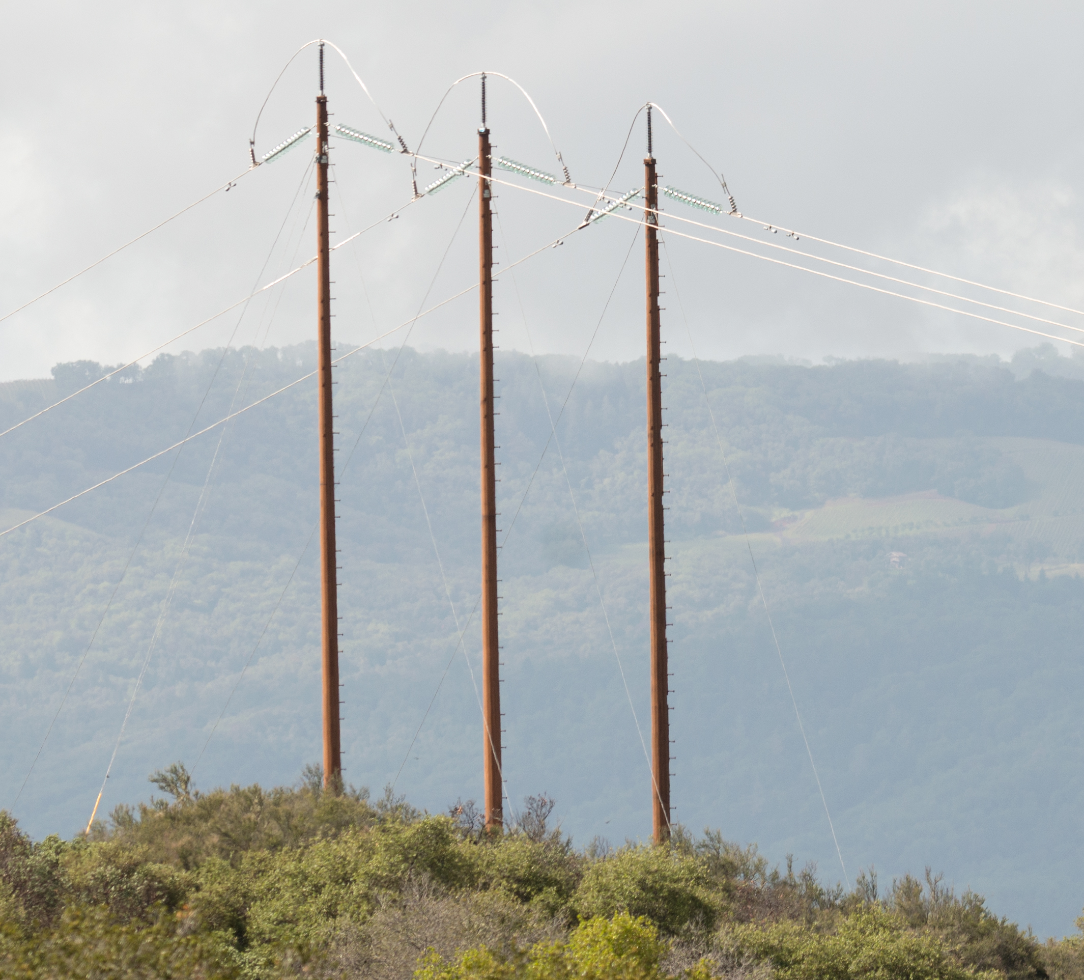
|
New Steel Transmission Poles 20 June
2019 laying on the ground. The old wooden poles
still standing. I'm guessing this is so that in the event of a fire the pole will not burn.. The problem is steel gets weak when heated so may slump, but that better than dropping the line on the ground. Taken with G6 cell phone from parked car. See Ukiah 29 June 2019 PG&E Poles - Fig 45 photo taken with Nikon D800E using 200mm f/4 lens hand held. Then cropped. I tried this with my cell phone but when zooming in there was a fuzzy image. Click on the Close Up to see more detail. |
|||||||||||||||||||||
Fig 38
Excavator at top of hill why? |
There has been a lot of PG&E work
for the past few months where they are installing new
wooden distribution poles next to existing wood
poles. The new poles are larger in diameter and
maybe taller, but the new wires are considerable
larger. Maybe to make it less likely they will
break if a tree branch falls or maybe because the
whole US electrical grid need to double in
capacity if gasoline is going to be replaced
with electricity from the grid. Probably the
former reason. When the new hole is dug, it is NOT using an auger, but rather a wand with I assume compressed air/water. Maybe because the new pole is right next to the old pole, or maybe it's a better way to dig the hole? Ans: to avoid underground utilities Used to dig holes for the 3 new transmission poles (not a tower). |
|||||||||||||||||||||
Fig 37
2021 Oct 22: Replacing distribution wood pole next to
the HV lines & Water Pump |
The PG&E electrical outage map
shows: Start Time: 9:01 am Estimated restoration: 5:00 pm Customers affected: 35 A month ago I received two letters saying my power would be out for a pole replacement, both times it did not happen. So this time the power outage happened, but there was no warning letter. |
|||||||||||||||||||||
| Fig 39 New
Transmission Poles on next ridge |
New steel poles (not lattice type
towers) replaced the wooden poles and cross arm on the
next hill over. |
|||||||||||||||||||||
Fig 41 Voltage
Regulator |
YouTube: T&D PowerSkills: |
|||||||||||||||||||||
Fig
42 2022-01-25 New Voltage Regulator in Ukiah |
There is an existing apartment complex
behind the voltage regulator and an apartment complex
under construction across the street. This is
the second day of the install. |
|||||||||||||||||||||
Fig
43 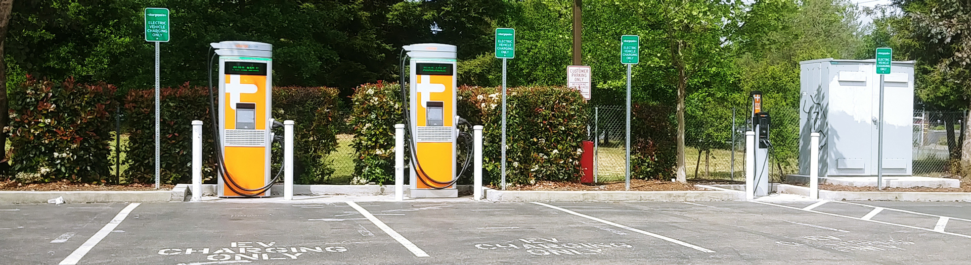 |
Burger King (Perkins
St, Ukiah, CA) Hi & Lo power EV charging Located less than a minute from the 101 freeway. 4 cars can be at the two high power charging stations at the left. 2 cars can be at the low power pedestal on the right. Note massive transformer to the far right. |
|||||||||||||||||||||
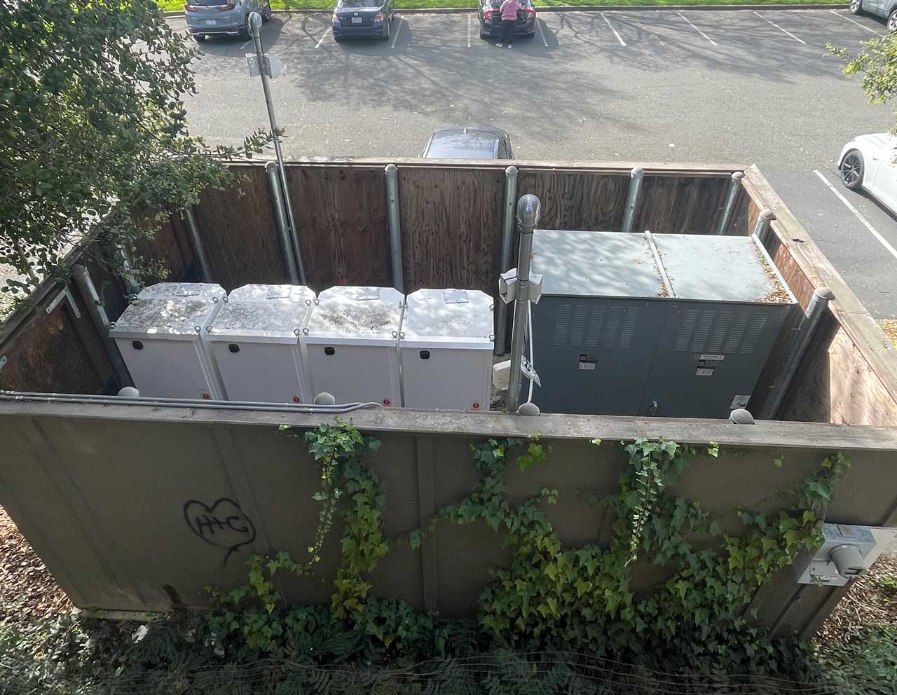
Fig
43B Eight Station Tesla Supercharger (Wiki)
- downtown Ukiah
|
There are 8 charging stations and 4
white cabinets. Because two charging stations share an equipment cabinet these are V2 (125 - 150 kW) charging stations. (4 of the V3 chargers share a single cabinet. The larger SquareD box to the right is probably to organize the wiring. Note the pad mounted transformer (also see Fig 51) behind the charger. |
|||||||||||||||||||||
Fig 46
|
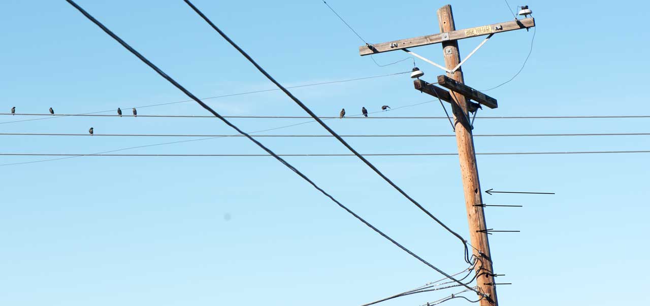
Woodpecker Hotel Arrows point so some of the rooms made by woodpeckers. I don't think the birds on the wire are woodpeckers and I've heard may be using the holes. Vulture 2024 Jan 5 Noon Sunning |
|||||||||||||||||||||
Fig 47
|
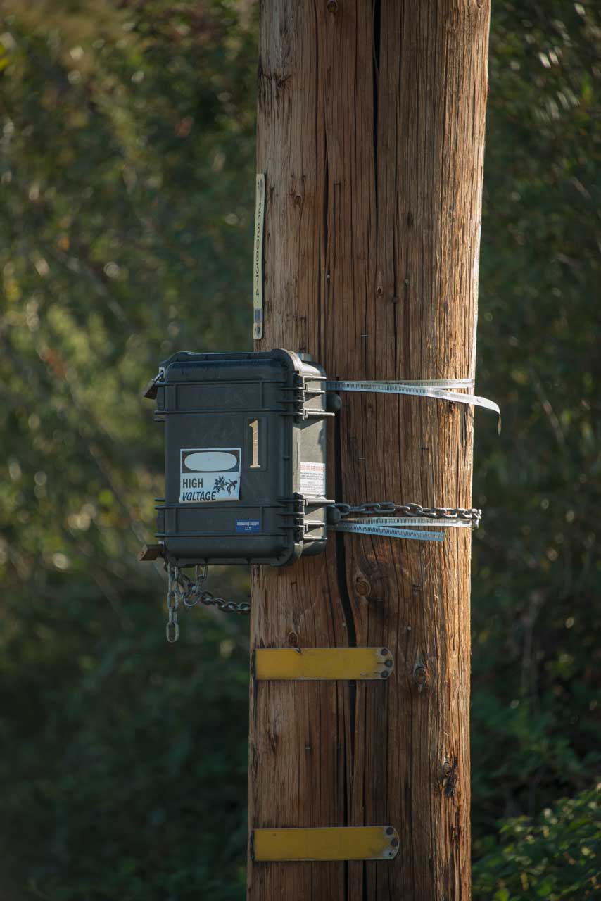
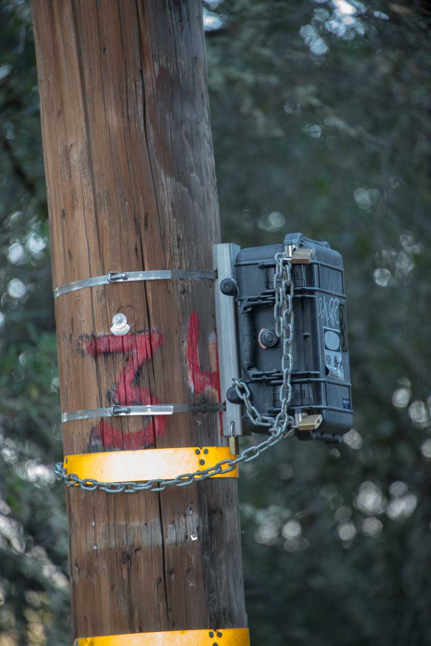
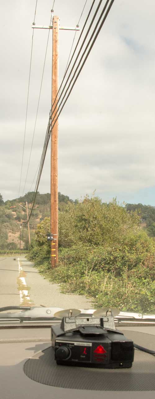
Black Boxes Chained to Poles The left two photos are of one of the boxes and the phone & HV lines above it. I do not see any connection between the lines and the box, but the box is labeled Danger High Voltage. The box in the left photo is 0.4 miles before the Flock Crime Solving camera and the box in the right photo is 0.5 miles after the Flock camera. Both boxes are pointing at the road (they could be mounted behind the pole to be less visible) and mounted at about the same height as a car window. They appeared a month or two after the Flock camera was installed. There's a good possibility that these are speed monitoring boxes the replace the old dual rubber hose system. This allows the local authority to see how fast people are going. But when coupled with the Flock camera can be used to hand out speeding tickets. The Valentine 1 Radar Detector shows that these are in fact traffic radars. I'm guessing that the two radar car counters (the signal seems weak for a speed radar) on either side of the Flock camera may be to audit it's counts. The RADAR signal comes out of the right side on both units. |
|||||||||||||||||||||
Fig 50
Click on image for top of the pole close up. |
Fault Indicator (3 Rapid Red flashing
Lights) 20120146661 Fault indicator capactive power source, Kirk Thomas, 2012-06-14, - cited by 11 patents When power is present a current transformer charges a capacitor. When the AC line is off the capacitor powers the flashing LED. Schweitzer, Eaton, ABB, Schneider |
|||||||||||||||||||||
Fig
51 Pad Mounted Transformer (Wiki)
|
At the time I took these photos I
suspected this was a box holding Fiber Optic cable. But it turns out to be a pad mounted AC transformer, part of the electrical grid. So I've moved it from the The End of AT&T Landlines web page to here. |
|||||||||||||||||||||
| Fig 52.
Helicopter N216AP
lifting PG&E pole - 2024 March 18 working with N410AP. White buildings in background are a pot grow.  |
||||||||||||||||||||||
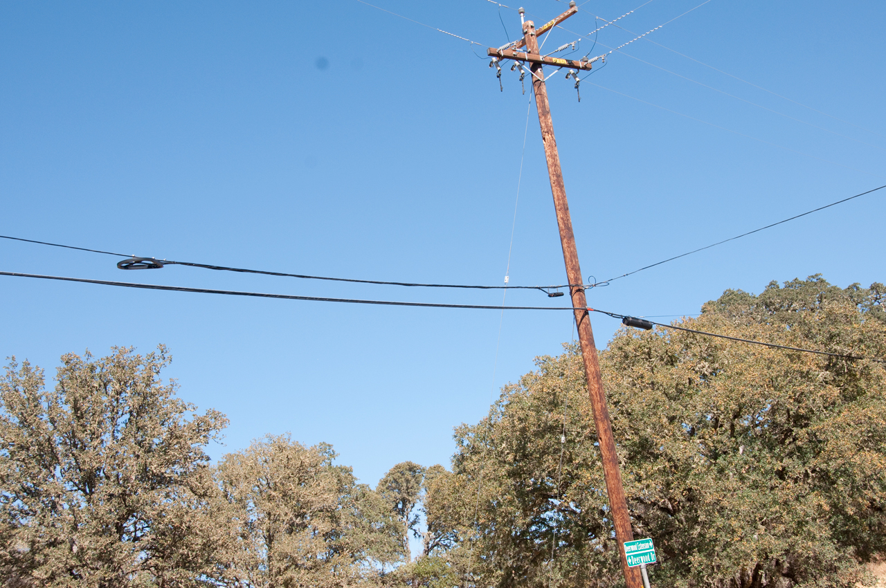
|
Telephone line in left photo, with
yellow streamers, is very low. The cause is the pole behind the camera that took the left photo, shown in the right photo. It's leaning to the left even though it has two steel support cables. Maybe this is why my DSL has not worked for the past few months? |


Hybrid Fibre-coaxial (Wiki)
Instead of the old fashioned cable TV system where only coax was used the system Comcast is using here is called Hybrid Fibre-coaxial. The frequency compensating line amplifiers have been eliminated by installing nodes every mile or so and running coax to the subscribers where the length of the coax run is short enough that no amplifier is needed. The system is based on the General Instrument, Jerrold Starline BTN-M Broadband Telecommunications Node. As far as I can tell this box can use either coax or fiber (Wiki) in the path from/to the headend (Wiki) or downstream. At the headend (Wiki, CMTS) there are multiple fibers connecting to the internet. There are up to four coax I/O ports that can go to subscribers. The classical cable TV system was one way from the headend to the subscriber, but for internet a two way system is needed.
YouTube: Cable Television Node- inside the Fiber - Coax node box
5 - 200 MHz for Return (Up Load) and 50 - 750 MHz for Foreword (Down Load).
If one TV channel takes up 6 MHz then slightly more than 100 channels are available for a single path. Maybe twice that if a "split" system is used?
DOCSIS 3.0 (Wiki) is the current cable modem standard. In versions prior to 3.0 only one TV channel was used limiting the bandwidth, but now at least 4 channels are supported with no maximum number defined. With 4 channels the max download throughput is 152 Mb/s (what Comcast advertises for is small business service).
There is an impact of this wider bandwidth on the Wireless router (Wiki) that you attach to the modem. The first generation routers only worked at 2.4 GHz and only supported a limited amount of bandwidth. The newer routers support multiple channels on both 2.4 and 5.8 Ghz allowing a number of people to have simultaneous connections.
PS I looked into Mobile broadband modems (Wiki) but they have data caps and only work with a reasonably strong cell phone signal. Something I do not have.
7039317 Reconfigurable node for a hybrid fiber cable network, Marlin McGregor, General Instrument Corporation, May 2, 2006, - the Starline BTN-M node
Note that two fibers are used in this system. One for download and one for upload so the system is potentially symmetrical unlike ADSL where the "A" stands for asymmetrical. This allows for high speed uploads, like needed for video broadcasting (i.e. a Youtube channel).


Fire & Vegetation
On 8 October 2017 there was a forest fire very close to my house. We heard from the sheriff that the probable cause was a tree knocking down a power line. But today I read an article that said ""The utility company is charged with maintaining its power lines and the vegetation around them to prevent wildfires." I don't think that sentence applies to trees falling on power lines, but rather to preventing the High Voltage lines (not eht 220 volt lines that feed houses) from touching vegetation. Note that if the High Voltage lines touch vegetation the electrical arc can state a fire. So, as far as I know, they maintain a ten foot separation.
I've asked the authors of the article to clarify this.
Pacific Intertie DC power transmission system
This is a DC power transmission system (Wiki).
It might also be used for ELF communications with submarines?
3993989 ELF communications system using HVDC transmission line as antenna, Gedaliahu Held, K. R. Ananda Murthy, TRW, 1976-11-23, - cites 9 patents (MSK), cited by 25 patents - uses a coupler, like for campus carrier current (Wiki) AM ratio station
Related
FasTrak Vehicle ID Transponder - is an active transponder, not an RF ID tag.
Harris TS1000 ADSL Test Set
Key, Object & Pet Location Tags -
Spying on Cell (Mobil) Phones
Orion Electronics Ltd. Cellular Base Station ST616-CBS
Telephones
Telephone Tool Kit
Telegraph
Smart Electric Meters
Inductors
Capacitors
Impedance
Impedance of transmission lines below their cutoff frequency
Rural Internet (depends on DSL or Cable Modem) - point-to-point WISP service only for those who live on hill tops.
Tempo Sidekick T&N Telephone Line Tester
KS8455L2 Line Loop Tester Telephone Installers & Repairman's Meter
ZM-11 Bridge
Ubiquity NBE-2AC-13 2.4 GHz Wireless Point-to-Point Broadband
VOIP - Voice Over Internet Protocol
N. McLain: OutSide Plant article (pdf), Utility Poles in General (Web page), UPRR abandoned poleline (webpage)