Austron 1250A Frequency Standard
© Brooke Clarke 2015Description
Photos
Operation
Upon Receipt
Related
Links
Background
This is part of my passion for Time and Frequency. Frequency standard frequencies started out in the audio range with very large crystals and have moved up in frequency over time. The current frequency for standards is 10 MHz and the prior frequency was 5 MHz. So this standard is at the prior standard frequency. The dates associated with this 1250A are 1984 (contract date) and 1987 (manual date).
Crystal oscillators exhibit some long term drift and so when used in stand alone applications require periodic calibration. They can have excellent phase noise (low distortion) and so are the oscillators used inside the atomic frequency standards based on Cesium, Rubidium, Hydrogen, &Etc. Where the atomic physics package acts to discipline the quartz crystal oscillator. Another way to discipline an crystal oscillator is to use a time signal, like WWV, WWVB, LORAN-C or GPS.
Description
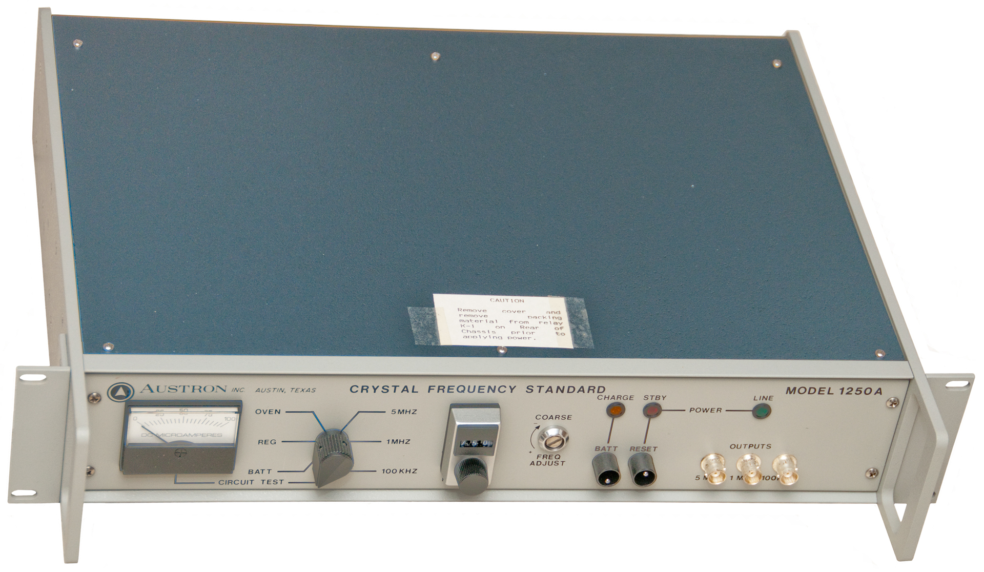
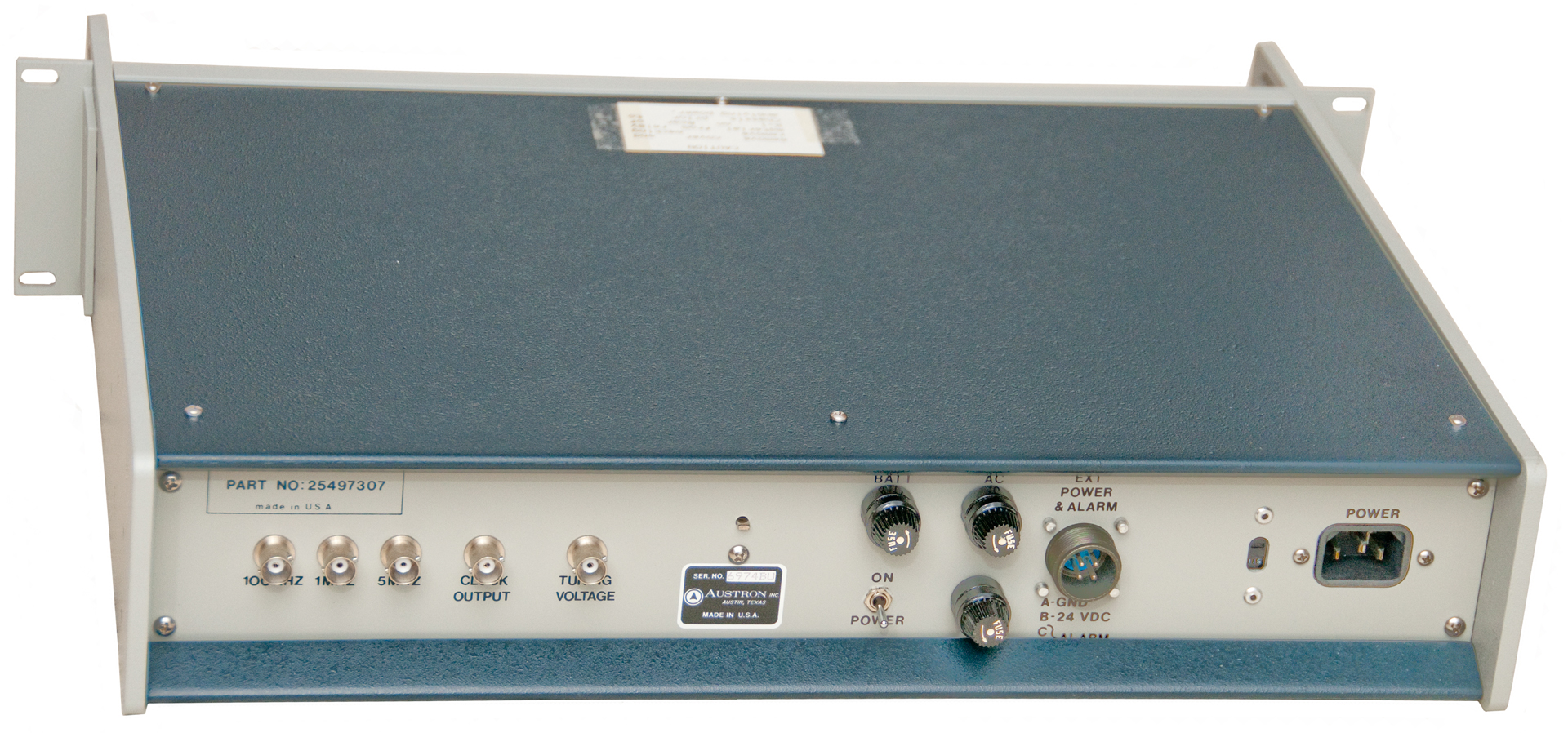
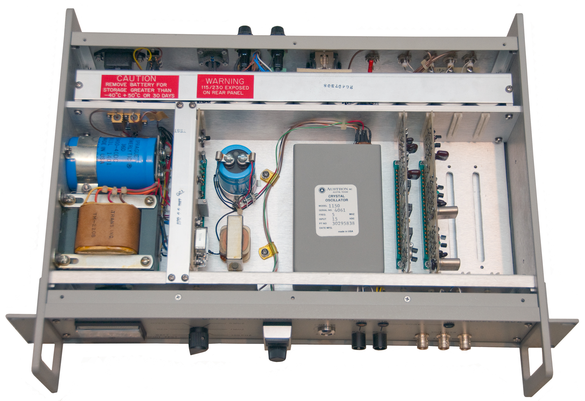
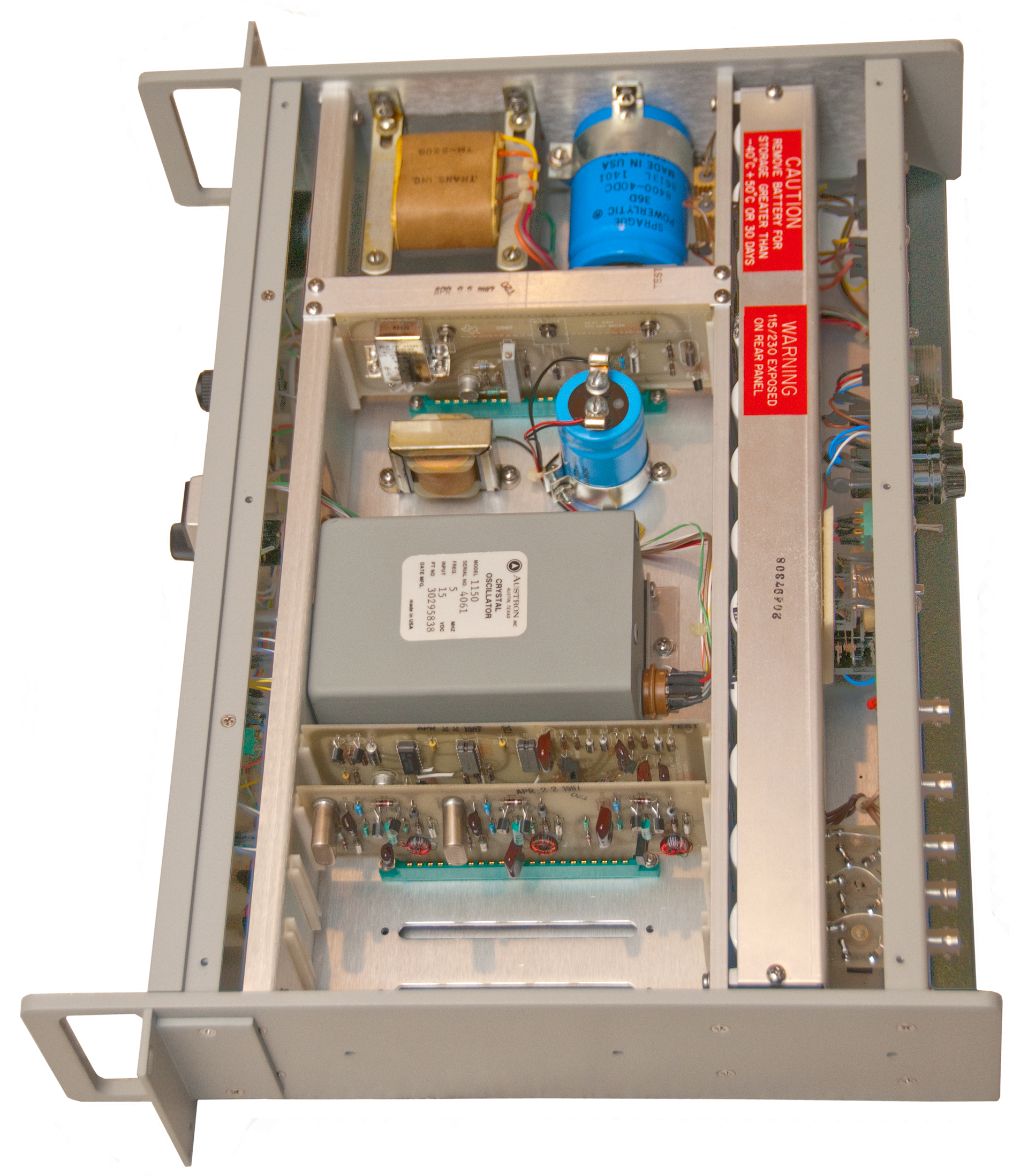
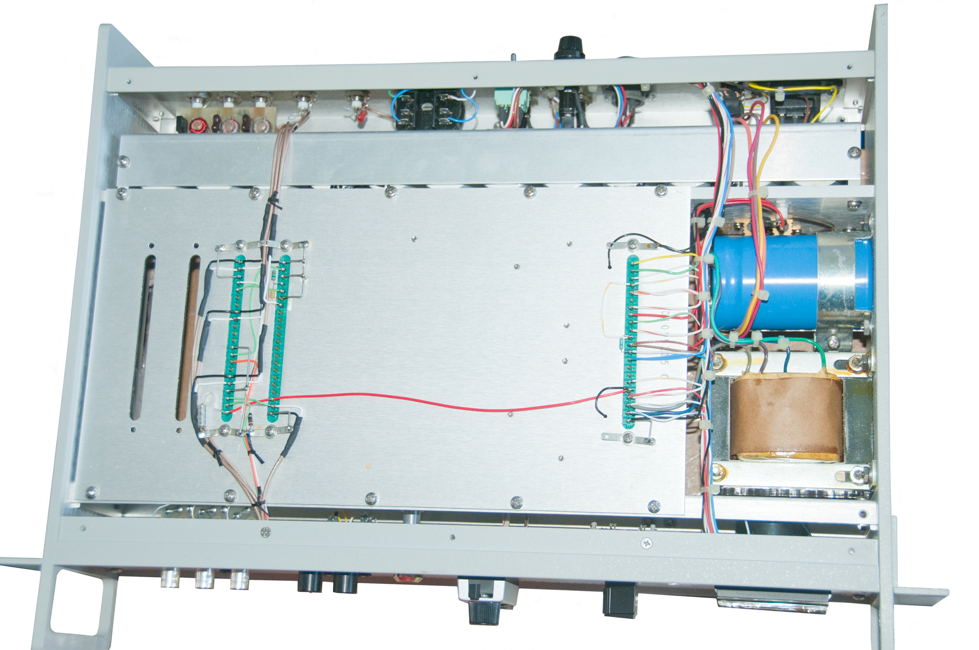
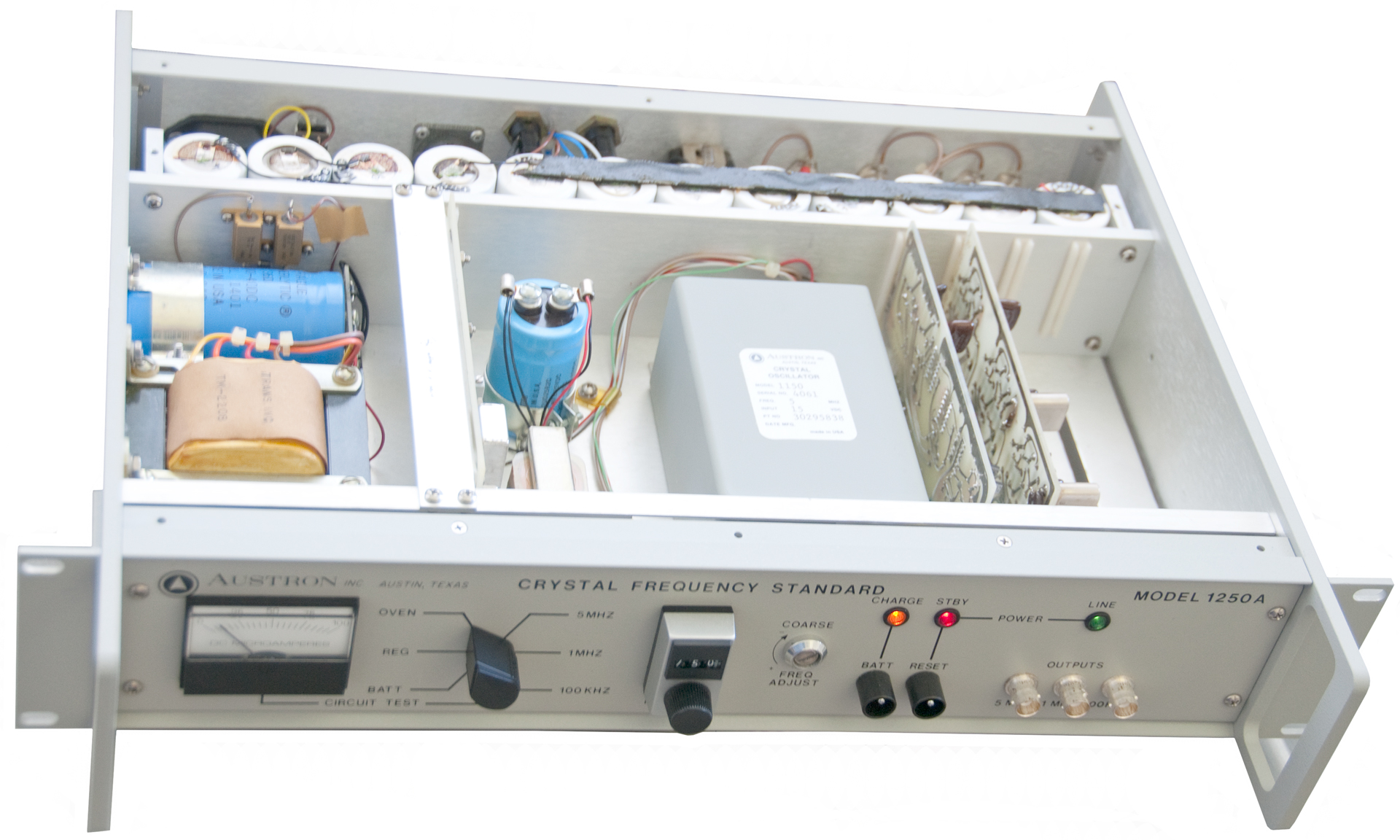
This is a rack mount 5 MHz frequency standard. In addition to the Austron model 1150 Five megacycle proportional controlled ovenized oscillator it contains a AC line power supply, provision for an external 24 Volt supply and an internal Ni-Cad 12 cell (14.4 Volt) battery pack with both trickle and charging circuits. There are also dividers to provide outputs of 1 MHz and 100 kHz. The chassis has a couple of unused card positions for other versions of the 1250 or maybe frequency standards with another model number? There is also an input for electrically tuning the oscillator. Note the front panel fine frequency control is a 10 turn pot which is driving the fine tune capability of the 1150 oscillator. The Coarse frequency control has a front panel cap the needs to be removed (which is for thermal stability) and then the tuning tool supplied with the accessories kit can be used to make coarse adjustments.
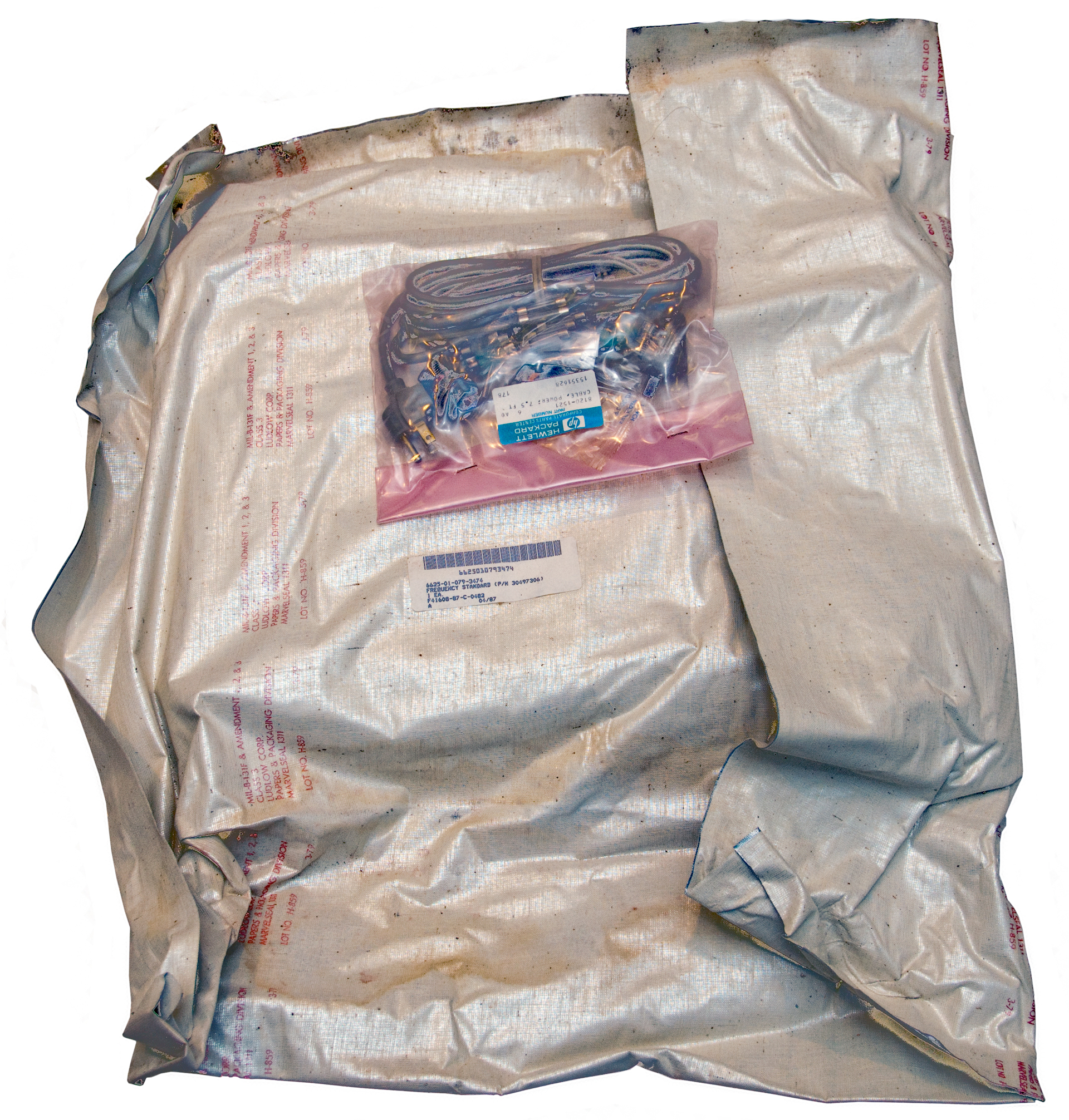
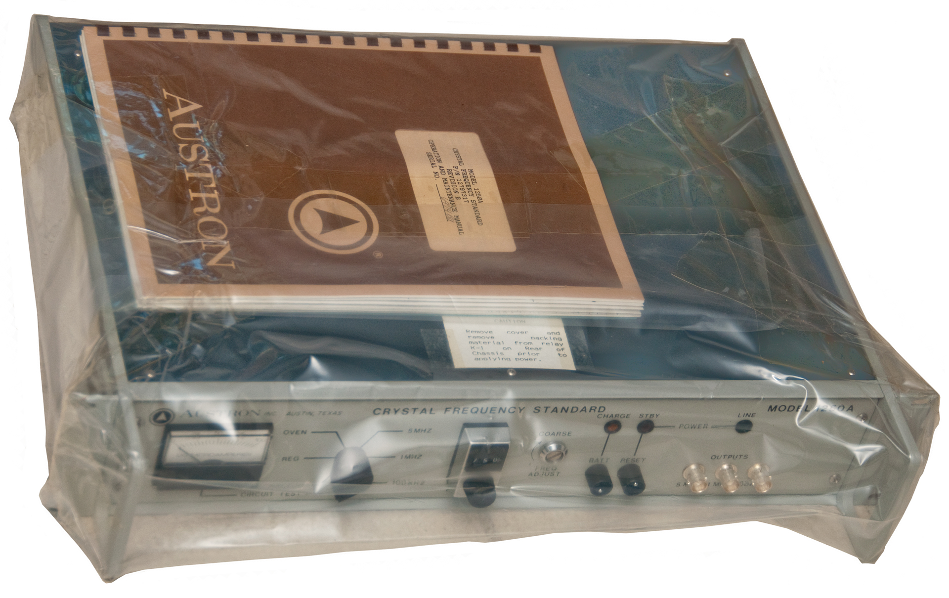
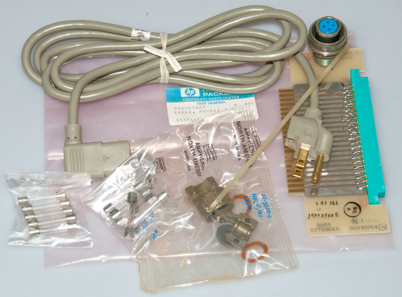
This 1250A came New In the Box (NIB), but after seeing the very poor condition of the box I thought I might be getting a "project", but it turns out that this was a government contract unit in full mil specification packaging that included foam in place packaging. Inside that there was the multiple layer metalized and hermetically sealed bag with desiccant (Wiki) bag. In addition there was plastic bag marked Hewlett Packard with the line cord, fuses, auxiliary DC power connector, &Etc (Why the HP brand name?). Inside that there was a plastic bag surrounding the 1250A and the manual.
Options
-01 p/n 30497306-1 Separately buffered, jual outputs to the rear panel. A8 is added to the left blank slot.
-02 p/n 30497306-2 Seven separately buffered 1 MHz TTL outputs, one on the front and six on the rear panel. No 100 kHz outputs. A9 is added to the right blank slot.
Controls and Indicators
Meter - Marked 0 to 100. Typical reading when oven warm is near 50 for all functions of switch.
Meter Switch: positions: Battery, Regulator, Oven current, 5 MHz amp drive, 1 MHz amp drive & 100 kHz amp drive.
Fine Freq - parts in E-10
Coarse Freq - total range > 300E-9 (use tool p/n: 02096081 in accessories kit)
Battery - normal (down) position for trickle charging, up position for fast charge.
Charge lamp - orange for fast charge, off for trickle charge
Standby - Reset switch - momentary switch that disables Standby after AC power is applied.
Standby lamp - Orange indicates that the primary AC has failed. (once battery is charged toggling this switch turns off the lamp. Related to the rear panel AC fail relay)
Line lamp - green indicates AC line power good.
Outputs: 5 MHz, 1 MHz , 100 kHz sine wave @ > 1 Volt into 50 Ohms. The Clock output is 1 MHz > 0.5 Volts into 1 k Ohm.
Fuses are 1 Amp slow blow
On/Off switch - rear panel switch for AC and both internal and external batteries.
External Power & Alarm - pin-A batt. ground, pin-B +17 to 35 V ext. batt., pins C & D relay that closes when the AC fails (5A 230 VAC max).
IEC AC line input jack.
Photos

Operation
Upon Receipt
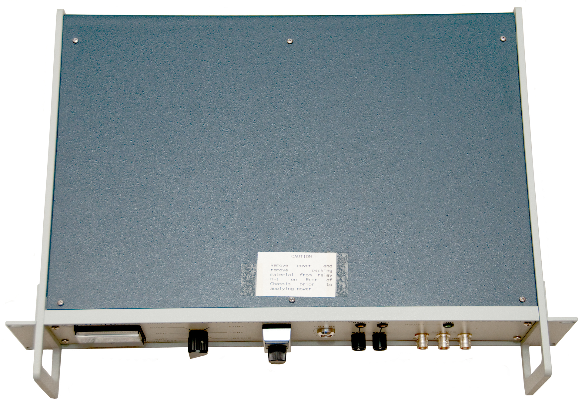
As per the notice on the top remove the top cover and the foam spacer between the rear panel and the large relay.
I also removed the top cover over the batteries so that I could measure the voltage of two adjacent cells. To do this remove a screw at each end of the top metal bracket and it up (there's double sided rubber tape between the bracket and the batteries). Note if you measure the voltage between two cells next to each other you will read either zero because there's a jumper on the top, or the voltage of two cells because there's a jumper on the bottom. This idea is to look for shorted or open cells, I found neither (a good thing).
Plug in the line cord and switch on the POWER using the rear panel toggle switch. At this point you can hear a relay chattering. It's not the rear panel relay but rather the K1 relay on the power supply board. Next turn up the BATT toggle switch to CHG and then hold up the RESET switch which then stops the chattering relay, but as soon as the RESET switch is released it's momentary action turns off the RESET and the relay starts chattering again. So I looked for something to wedge the switch up and after trying a number of things thought I had found something that worked, but it didn't feel correct to pulled it out and the chattering did not resume. So I think that if you just hold the RESET switch up for a minute or two enough charge gets into the battery to allow normal charging. I unplugged the 1250 at night since the top and bottom covers were off and there was a remote chance of a battery fire. Turned it on in the morning for more charging. The Fig 11 photo was taken shortly after the morning power up. As you can see in the photo lamps are on CHG (orange), STANDBY (red) and LINE (green).
The meter reads:
Meter
Oven Cold
Oven Warm
Batt1
57/52
Reg
53
Oven
20
5 MHz
45
1 MHz
42
100 kHz
42
Note1: The battery test can be done with the BATT switch set to Charge or with Charge off.
Meter reading 57 (charging) corresponds to 16.08 V across the smaller electrolytic cap.
Meter reading 52 (trickle charge) corresponds to 13.77 V ". Which is not quite charged.
Related
117A HP 117 WWBV time standard receiver
5060A HP 5060A Cesium Frequency Standard
A1290 Austron 1290A 24 Volt Standby Power Supply
A2042 Austron 2042 LORAN-C Simulator
A2100F Austron 2100F, 2100T LORAN-C receivers & other Austron time and frequency instruments
DAGR - Defense Advanced GPS Receiver
Disosc Disciplined Oscillator Patents
FEIFS Frequency Electronics Inc. Frequency Standards FE-5650, FE-5680
FTS4060 FTS 4060 & Datum 4065B Cesium Time and Frequency Standard
HeathkitGC1000 Heathkit GC-1000 Most Accurate Clock & 3.6 MHz frequency standard - my oldest disciplined oscillator
HP 117A HP 117 WWBV time standard receiverHP5100 5110A Synthesizer Driver & 5100A Frequency Synthesizer
HP5060A HP 5060A Cesium Beam Frequency Standard
HP8648 HP 8648A 100 kHz to 1 Ghz Signal Generator w/ pager option\
HP33120 15 MHz Function/Arbitrary Waveform Generator
HPE1938 HP E1938 Ovenized Crystal Oscillator - isothermal design
HP Z3805A Time & Frequency GPS Receiver
Jackson Labs - LTE-Lite GPSDO Evaluation Kit
Loran-C U.S. LORAN-C Chains
LoranPat LORAN-C Patents
Lucent KS-24361 HP/Symmetricom Z3809A, Z3810A, Z3811A, Z3812A GPSDO System
Nav Navigation Orientation & Position - precision frequency drives precision time which drives determining where you are
O1814 O-1814/GRC-206 Pacer Speak optional Rubidium Frequency Standard
PLGR PLGR GPS Family
PLGR-II Rockwell HNV-2000 PLGR II SPGR GPS Receiver
PRS10 PRS10 Rubidium Frequency Standard - will discipline itself if given a 1 PPS input
PSN-6 R-1897/PSN-6 Loran Receiver
PSN-8 PSN-8 GPS receiver
PSN-9 GPS receiver
PSN-10 SLGR GPS receiver
PSN-11 PLGR GPS receiver
PSN-13 DAGR GPS receiver
PST1020 Precision Standard Time Model 1020 WWV Receiver
Q5200 Quantic Q-5200/SM Timing GPS Receiver
QuartzClk Quartz Kitchen Clock Movement
Rockwell Trooper GPS HNV-600
Rockwell HNV-2000 PLGR II SPGR GPS Receiver
TandFTE Time & Frequency Test Equp:
TF_rack Time & Frequency Rack annotated photo - includes some clocks driven that can be driven from a frequency standard
TimeFreq Time & Frequency
Xam Crystal Activity Meter
Xec Crystal Unit Equivalent Circuit
Xtal Electronic Crystals
Xtal1800 Crystal Radio 1800? & Brooke Clarke #1
Xtc Crystal Temperature compensation Patents
Links
PRC68, Alphanumeric Index of Web pages, Contact, Products for Sale