Much of the following operational and engineering information is
from analyzing how the radio works and does not appear in any of
the manuals.
The May 1977 copy of FM 24-24 lists the PRC-68 as a developmental
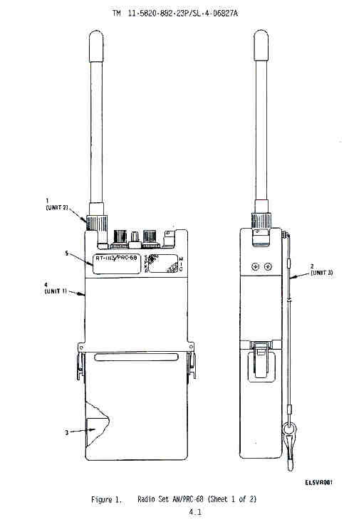
item and has a crude sketch rather than the common
photograph. The antenna is listed as telescopic built into
the radio (which was changed to the PRC-25 type antenna or a
rubber duck).
1.1 Equipment Description
1.1.1 Purpose of Equipment
The PRC-68 was a development of the U.S. Marine Corps and they accepted it in 1975. Radio Set AN/PRC-68 (radio set) is a hand-held receiver-transmitter that provides ground-to-ground voice communications in the 30 megahertz (MHz) to 79.95 MHz band. The unit is capable of secure speech operation when it is used with the Secure Voice Module (SVM). The radio set can be used with a short or long antenna, with a standard military handset such as H-138/U, H-189/U or H-250/U, or with its built-in speaker-microphone.1.1.2 Characteristics, Capabilities and Features.
The physical and electrical characteristics of the radio set are given in 1.3 Table of Specifications.First Military radio to use Battery Saver
This may be the first military radio to use a frequency synthesizer on a chip, the PRC-25 uses discrete components to implement its frequency synthesizer which requires about a dozen crystals, but the PRC-68 only needs 1 crystal for the local oscillator chain.The receiver is turned on and off at a rapid rate thus saving battery power when no signal is being received. Also the audio output amplifier is turned off when there is no received signal.
Special capabilities and features of the radio set are as follows:
a. Preset Frequency Channel Capability - The radio set is able to be internally programmed with ten (10) preset f requency channels with 200 kHz spacing covering a 2 MHz bandwidth. One setting of the frequency programming switches establishes all 10 channel assignments.
b. Warning Tones - The PRC-68 does not generate warning tones. (This may be a good thing in a close combat situation.)
C. Antenna Matching Switch - The PRC-68 does not have an ANT matching switch. Internal adjustments need to be made using a Field Strength Meter (FSM) whenever the channels are reprogrammed. This is the only radio in the series with the ability to tune the antenna and so this radio can use many more antennas than the others that need to have the correct length antenna. This is an advantage for the PRC-68.
d. Liquid Crystal Display - The PRC-68 does not have an LCD.
e. COMSEC Operation - Provides 16 kb VINSON compatible secure voice operation by simple attachment of the KYV-2() NSA approved COMSEC device between the radio set and battery.The prior sentence is taken from the radio manuals, but the comments (see Links below) indicate that the radio is NOT capable of secure operation. This may be because of some problem with the KYV-2 or maybe just some other reason like the KYV-2 modules were not available in the needed quantity. The PRC-126 does not frequency hop like the SINGARS and other modern military radios.
This was the first in this series of radios and is smaller than the others. It also uses many modules whereas all the later variants have only two modules.
1.1.3 Construction
Like the PRC-25 the PRC-68 uses mostly discrete components in a modular construction where each module preforms a single type of function. In all the later varients there are only two modules. This is much more efficient in terms of getting more functionality into the same space. A flexable circuit is used to make connection to the controls on the panel rather than use hand wiring, but all the other wiring uses wires and there are two printed circuit boards in a back to back arrangement to connect to the two modules. One of these is fixed to the radio and the other is removable.This was the first radio in the PRC-68 Family.
1.2 Photos
| Top - there are just 5
terminals on the audio connector, matching the H-250
handset (6 on later models) pin E on the AUDIO connector is
for vehicle power. The radio draws more than 300 mA
but less than 500mA. When using pin E for power the radio operates with the switch set to OFF! This is the way they decided to save the batteries. The antenna connector has a 5/16" x 24 threaded hole. If someone hands you a PRC-68 radio there is no way, short of opening the module housing, of determining what frequencies is has been programmed for. The PRC-68A is even worse, you need test equipment to determine how it has been programmed. On all the later radios there is an LCD that displays the Rx and Tx frequency as the band switch is changed.  |
||
| Front with cover, no LCD frequency indicator and no antenna coupler rotary switch  |
Back with cover, 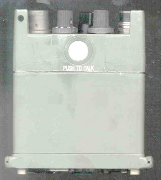 |
|
|
Bottom with cover - On the bottom of the case there is a small screwdriver used to set the switches inside and a cavity for the jumper plug when the voice encryptition unit is installed.  |
||
Front3 - will all
modules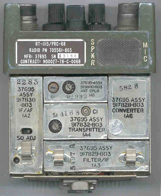 |
|
|
Front - with no
modules installed |
||
Back with all modules |
|
Back - with no modules
installed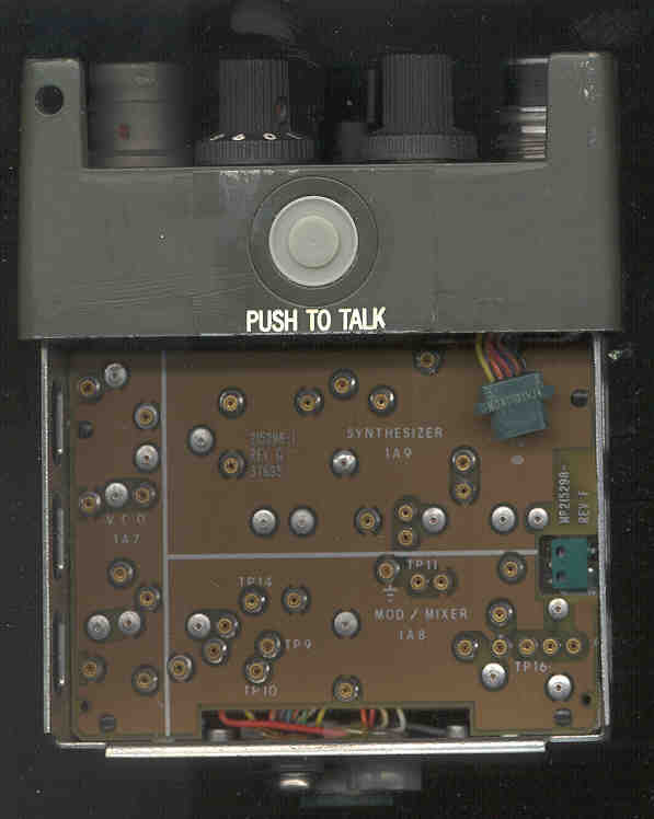 |
| On the edge of the printed
circuit board about in the center is the "push to tune"
switch used to set C1 on the 1A4 Tx module. In furture versions the above 5 modules will become a single module mounted on the back. To program the 10 channels the module cover needs to be removed. |
 |
1.3 Table of Specifications
General Specifications
Frequency Range 30.000 MHz - 79.95 MHz Available Channels 1000 in 50 kHz increments Minimum Channel Spacing 50 kHz Preset Channels 10 adjacent Modulation Frequency Modulation (FM) Operating Temperature Range -40 deg F to +159 deg F (-40 C to +65 C) Weight (battery, antenna included) 40 oz (1.3 kg) Size 8.35" (212.0 mm) x 3.8" (96.0 mm) x 1.52" (38.6 mm) Communications range - long antenna & goose neck 1.0 mile (1.6 km) Communications range - short (rubber duck) antenna 330 Yards (300 meters) Typical power consumption 47 mA when in receive mode with the radio quiet (0.8 AH for NiCad batt / .047 = 17 hours of Rx only time) 84 mA when VOL is set at max and radio driving internal speaker (9.5 hrs of listen only time) 450 mA when transmitting (1.8 hrs of Tx only time) Transmitter Specifications
Power Output 1 Watt Frequency Control Built-in Synthesizer Frequency Stability 0.005 percent Spurious and harmonics radiation 50 dB below RF carrier level Modulation Limiting +/- 15 kHz Dev max 148 to 152 Hz Squelch Tone 2.5 to 3.5 kHz deviation Receiver Specifications
Adjacent Channel Rejection -60 dB Image Rejection -40 dB Sensitivity 0.5 microvolts for 10 dB SINAD Squelch sensitivity 0.5 microvolts Selectivity, 6 dB down bandwidth greater than +/- 15 kHz , 60 dB down bandwidth less than +/- 50 kHz Response to Spurious Signals -60 dB Audio Output less than 10 % distortion at 20 milliwatts
SINAD = (Signal + Noise + Distortion) / (Noise + Distortion) Squelch although 150 Hz is sent during transmission
the receive squelch operates based on signal not 150 Hz tone.
3.1 Introduction
Because of it's size the PRC-68 will not fit into a shirt or pants pocket (maybe a battle fatigue pants pocket). Your choices are hold it in your hand all the time, OK for some uses, or use the carry bag connected to a military pistol belt and use the H-250 handset, or in quiet locations where you can hear the built in speaker, the M-80 Microphone.3.2 Controls, Indicators and Connectors
Each operating control, indicator and connector on the radio set is identified in the photos above and described in paragraph 3.4.3-3 Frequencies with Reduced Sensitivity
The following frequencies have receiver sensitivity reduction (the squelch may not quiet).
If they are selected during testing in Section 5, erroneous readings may result.
If they are used in the field the reception range will be greatly reduced.
BOLD frequencies are unusable.
30.00 40.00 50.00 60.00 70.00 30.70 40.25 51.25 60.05 70.55 31.20 41.20 53.20 61.00 70.70 32.00 41.80 53.25 61.35 71.00 32.15 41.85 54.00 62.40 71.45 33.15 41.95 54.60 62.50 73.00 33.40 42.00 54.85 62.95 73.40 33.60 42.25 55.20 63.20 73.65 34.40 42.75 55.25 63.40 74.00 35.00 43.15 55.50 64.00 74.40 35.95 43.9 55.65 64.85 75.00 36.00 44.40 56.00 65.10 75.05 36.05 45.15 57.20 65.20 76.90 36.15 45.60 58.30 66.00 77.50 37.00 45.90 59.30 66.35 78.00 37.50 46.00 59.95 68.05 78.50 37.95 46.75 68.20 79.10 39.20 47.35 69.75 79.40 47.50 79.50 47.65 48.30 49.05
3.4 Description of Radio Set Controls, Indicators and Connectors
Name Photo Description ANT connector Top Connects antenna (or 50 Ohm cable using 914598-801 adapter or 68AA) . CHAN selector switch Top Selects one of 10 preset operating channels. OFF/ON/SQUELCH DIS switch Top Turns radio set on (clockwise) or off (full counterclockwise).
The spring loaded SQUELCH DIS position will turn off the squelch as long as it is held.VOL Top Controls the audio volume AUDIO connector Top Standard U-228/U style 5 pin connector for use with external handset. PUSH TO TALK switch Back Enables radio set to transmit when pressed in normal operational mode. Battery Connectors Bottom Connects battery to radio set. SVM connector & Plug Bottom Provides interconnection between SVM and radio set.
Jumper Plug allows radio to operate when SVM is not installed.Speaker/Microphone Front Functions as a built-in speaker (receiver) and microphone (transmit) when external handset is not connected.
When an external handset or headset is connected the internal speaker will go into mute mode.3.5 Antenna Connection
The threaded hole that the antenna mates with has a 5/16" X 24 thread the same as the PRC-68A, PRC-126, PRC-128, and PRC-136 but different from the PRC-68B that has a 1/4" X 28 thread.3.5.1 Short Antenna
The Short Big Base Rubber Ducky antenna is used for communications to 300 meters.3.5.2 Long Antenna
Just the tape measure antenna is used for communications out to 1,600 meters.3.5.3 50 Ohm Antenna
When an external 50 Ohm antenna is used with an Antenna adapter to convert from the special radio connection to a standard BNC(f) connector switch S1 on the Antenna Coupler Module (1A5) should be set to "0" to disable the antenna matching circuitry. The PRC-68 does not have antenna DC sensing so it does not matter if the external antenna is a DC short or DC open. Some of the antennas and/or amplifiers that might be used are: OE-254 wide band biconical, RC-292 1/4 wave ground plane, OF-185 Power Supply/Amplifier, Diplexer, VHF, CU-2194/URC.3.6 DC Power
Note that the PRC-68 needs to be in the OFF position to work with external power! This way the radio battery is disconnected from the external supply. In later radios diodes will be used for isolation.
3.7 Handset
The H-250 Handset can be connected to the AUDIO connector. This allows the Squad Radio to be carried in it's Carrying Bag attached to a standard pistol belt.There is a flat on the handset connector. If this flat is positioned on and parallel with the PUSH TO TALK side of the radio it will mate with a small amount of rotation saving some time. This can be easily done by feel. This orientation of the AUDIO connector is true for all the radios in this family.
Other U-229 Audio accessories should also work with this radio such as the H-138/U, H-189/U handsets. Family photos of Audio Accessories.
3.9 Manual Channel Frequency Programming
By removing the module housing and inspecting the programming switches you can tell what frequencies are assigned to each of the ten Channels.
There are 4 switches used to control the frequency of operation of the PRC-68 called A, B, C and D.
Note
Because of the 50 kHz channel spacing it may not be possible to program this radio to some pre assigned frequency that does not fall on the 50 kHz steps.
The C switch is the 10 position CHAN switch on the top of the radio. The A, B and D switches are located on the Synthesizer module.To setup a channel:
The 10 position channel selector knob is the "C" and A, B and D are on the 1A9 Synthesizer modlule.After the channels are reprogramed the antenna coupling needs to be adjusted. This can be done using a Field Strength Meter like in the TS-3354 or PRM-34.
The programming table looks like:
(this table was printed on the battery cover for the PRC-68)
(these are also the settings for the channel swithces on the TS-3354)
Channel Switch A
(band)B C D Channel Sw 0 - 0.00 .00 .00 1 30.00 2.00 .20 .05 2 40.00 4.00 .40 .10 3 54.00 6.00 .60 .15 4 64.00 8.00 .80 - 5 - 10.00 1.00 - 6 - 12.00 1.20 - 7 - 14.00 1.40 - 8 - - 1.60 - 9 - - 1.80 - So to set the PRC-68 so that you can talk on 51.0 MHz the switches need to be set:
A=2, B=5, Channel knob = 5, D=0. Now the channels will be:
Channel Switch Freq 0 50.0 1 50.2 2 50.4 3 50.6 4 50.8 5 51.0 6 51.2 7 51.4 8 51.6 9 51.8 Note that 50.0 MHz is unusable, see 3-3 Frequencies with Reduced Sensitivity.
There are two parts to the procedure:
Transmitter "Tone" tuning
- Turn to "PWR OFF" before removing or installing the battery, remove the battery
- remove module cover
- remove the small screw driver from the bottom of the module cover for use in the following steps
- Connect battery and switch to "ON"
- while pressing the "Tone Tune" button
- adjust C1 on the Transmitter Module (1A4) for the lowest tone frequency
Antenna coupler Tuning for Transmit
The PRC-68 does not have a microcontroller (I thought it did for awhile) and so does not have any "special features" like the later radios in the family. In the case of antenna tuning this has advantages. The PRC-68 can be tuned up into a wide variety of antennas.
S1 on the Antenna Coupler module 1A5 noramlly is set to the same number as the synthesizer module 1A9 switch A, but there a few reasons not to:
(1) if you are going to use an external 50 Ohm antenna set 1A5-S1 to 0 disabling antenna matchingUse a feild strength meter like the TS-3354 or the TS-3951/PRM-34 or a receiver or spectrum analyzer with a remote antenna.
(2) if you are going to use external 50 Ohm test equipment set 1A5-S1 to 0 disabling antenna matching
(3) when tuning an antenna different from the stock PRC-68 antennas you might get better performance using a 1A5-S1 position a notch above or below the position of 1A9-A.
Select CHANnel 5 (band center) on the radio top panel.
Set Antenna Copuler (1A5) switch S1 to the same band as switch "A" on the Synthizer module (1A9) which is the same as switch S1 on the Transmitter module (1A4).
Adjust L1 on the Antenna Coupler module (1A5) for the strongest signal.Note: When using a 50 Ohm antenna set Antenna Copuler (1A5) switch S1 to "0" so as to disable the antenna matching function. Then the 68AA Antenna Adapter can be used with an external 50 Ohm antenna or with a direct connection to a test set.Squelch Adjustment
Turn the SQ ADJ pot on the IF/AF module (1A2) CCW until noise is heard, then turn slowly CW until noise stops, then go one more turn CW.Turn OFF, replace the small screwdriver on the bottom of the module cover and reinstall the module cover and battery.
3.10 Manual Split Tx & Rx Frequency Channel Reprogramming
The PRC-68 does not support split Tx and Rx operation.3.11 Reading (up loading) Channel Data
The PRC-68 does not support data transfer.3.12 Filling (down loading) Channel Data
The PRC-68 does not support data transfer.3.13 Repeater Operation
The PRC-68 does not support repeater or retrnasmission operation in the conventional military sense, but the Radio Shack 19-345 time offset repeater does work. When using the Radio Shack 19-345 and powering both the radio and repeater unit from a wall wart the current capacity needs to be 500 mA (the 300 mA power supply is not enough).The PRC-68 could be used as the transmitter with one of the 6 pin AUDIO connector radios acting as the receiver.
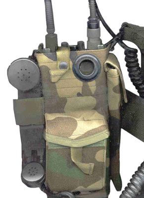
3.15 Carry Bag
Because of it's size the PRC-68 will not fit into a shirt or pants pocket (maybe a battle fatigue pants pocket). Your choices are hold it in your hand all the time, OK for some uses, or use the carry bag connected to a military pistol belt and use the H-250 handset. There are pockets for: radio, antenna, battery and a holder for a handset.Front Photo - showing a PRC-68 in the main pouch with H-250 attached and a spare battery in the front pouch. There is a place on one side to hold both antennas and on the other side a velcro flap to hold the Handset.
Back Photo - has two standard military pistol belt clips and will not attach to a standard civilian belt. The bottom of the main pouch has an insert so that when removed will allow for the extra length of the Secure Voice Module.
The original Operator's manual will also fit into the main pouch with the radio.
3.16 150 Hz Tone Disable
The PRC-68 does not support disabling the 150 Hz tone with the operator controls. When testing with the MK-2137/PRC-68 Maintenance Kit there is a 150 Hz notch filter. The 150 Hz tone can be disabled by shorting pin 9 on the Secure Voice Mocule connector.3.17 SPKR/MIC Mute Circuit
This is the circuit that puts a DC voltage on the handset speaker in order to determine if there is an external handset. If it finds that the resistance of the handset is below some value, then it mutes the internal speaker.3.18 Frequency Planning
When deciding on which frequencies to use in the range of a Squad Radio consideration should be given to a number of factors.
You may want someone to hear your transmission that has only a commercial receiver.
You may not want someone with a commercial receiver to eavesdrop on your transmissions.
- frequency allocations for the locality where the radio will be operated (some are on my freq allocation web page)
- avoid using frequencies were the radio may have spurious responses
- In areas where there are TV stations you may want to avoid using the frequency band for active channels. TV uses the same 100 kHz FM modulation as FM broadcast radio so if you tune to the audio carrier the signal will not be clear, but speech is understandable. By the same token you can transmit to a TV receiver tuned to one of these channels, and although not clear speech is understandable.
- TV 2 = 54 to 60 MHz, Video carrier = 55.25, Audio carrier = 59.75
- TV 3 = 60 to 66 MHz, Video carrier = 61.25, Audio carrier = 65.75
- TV 4 = 66 to 72 MHz, Video carrier = 67.25, Audio carrier = 71.75
- 72 to 76 MHz is not a TV allocation
- TV 5 = 76 to 82 MHz, Video carrier = 77.25, Audio carrier = 81.75
Another factor is the use of loop antennas for Direction Finding. The popular US models AT-339/PRC (38 - 55.4 MHz) and AT-748/PRC (30 to 76 MHz) range and do not completly cover 30 to 79.95 MHz. This may be a reason to use or not use the 76 to 88 MHz range.
- Many hobby scanner radios cover 29 to 54 MHz but not 54 to 88 MHz because of the above TV allocations.
- There are cordless phone frequencies in the 43 to 50 MHz range that might or might not be useful.
Compatibility with the PRC-68 would be improved if for example the PRC-126 used CHAN 5 for 51.0 MHz. That way both radios would have the same channel number for the same frequency. Note that the PRC-68 MUST have 51.0 on CHAN 5.
3.19 Antenna Planning
When these radios are going to be used for an operation, some thought should be given to the antennas for each radio whether used as a base, mobil, or repeater/retransmission radio. There is a tradeoff. using the ducky results in short range which may be a good thing depending on the circumstances.If you are looking for the maximum range, without going to amplifiers, then the best antennas and siting will be needed.
3.20 Speakers
It may be possible to use the military speakers like the LS-454 with the PRC-xxx series radios, but it would be awkward to transmit by using the radio's built in microphone. The amplified speakers AM-4979/GR and AM-6747/V have vehicle DC power inputs and a pass through connector setup that allows connecting either a handset like the H-250 or more practical a microphone like the M-80. The AM-4979/GR is specified for +28 VDC operation, but inside there is a 1N2976 12 Volt Zener diode, so it looks like it would work just fine on a 13.6 VDC standard car supply. A wire may need to be added from the 13.6 supply to pin E on the squad radio AUDIO connector to allow the radio to run off of car power.3.21 Sub Audible Tone
The PRC-68 transmits a 150 Hz tone so that it can talk with older radios like the PRC-25, PRC-77 and AN/VRC-xx radios that need to hear the 150 Hz tone to open their squelch. This tone is not used by ham radio operators for repeaters, so the PRC-68 can not operate on any repeater that needs a specified sub audible tone.The squelch in the PRC-68 works by carrier strength, not tone. This was done to avoid the squelch capture problem experienced by the PRC-25, PRC-77 and other radios that need the 150 Hz tone to open their squelch.
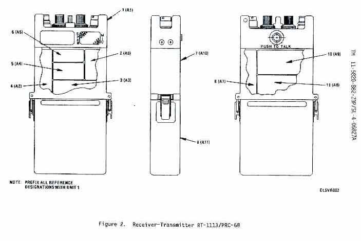
4.1 8 Modules
There are 11 Major components (8 circuit modules):
- 1A1 - Frame and Panel assembly
- 1A2 - IF/AF module
- 1A3 - Filter/IF module
- 1A4 - Transmitter module
- 1A5 - Antenna Coupler module
- 1A6 - Converter module
- 1A7 - VCO module
- 1A8 - MOD/Mixer module - contains a 12.0 MHz deviation oscillator
- 1A9 - Synthesizer module
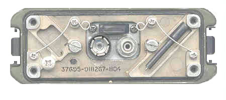
- 1A10 - Module Cover assembly
- 1A11 - Battery housing assembly
4.2 Block Diagram
Right side Block Diagram -
Left Side Block Diagram -
TSEC/KYV-2A Secure Voice Module (SVM is the Magnovox commercial designation)
The Jumper Plug which must be connected to the radio for normal operation needs to be removed so that the SVM can make connection to the radio.
Synthesizer
The brains of the radio is a custom chip in the 1A9 Synthesizer module. It functions not only as a synthesizer but also generates the battery saver waveform for the Rx mode. There is no LCD display on the PRC-68. There is not a EEPROM in the PRC-68.
For repair advice you can contact Jim Karlow, KA8TUR He might do a repair, but it is the third priority for him after his job and family.
TS-3354
The TS-3354 was designed for testing the PRC-68 but can be used with other Squad Radios in this family.TS-3951/PRM-34
This is a more modern version of the TS-3354 for use with newer 30 to 88 MHz squad radios.
This test set contains a frequency counter, power meter for forward and reverse and a comb generator to test receiver squelch as well as a field strength meter so that the PRC-68 antenna circuits can be adjusted.PS magazine -
462 - 43 - Antenna and Battery Bits -
434-45 - Antenna, Battery, PTT switch (A Good summary of PRC-68 PM) _ Do Not install a fresh battery with the radio switched ON! Do NOT cover the SPKR/MIC with you thumb when pressing the built in PTT.
427-23- Scribe Markes for PresetsMK-2137/PRC-68 Maintenance Kit
PRC-68 specific interface kit for bench testing the PRC-68Audio/Power Test Adapter
This has the following parts:The above circuit diagram is from TO 31R2-4_810-3 for the PRC-128.
- Red and Black clip leads for connection to a power supply that can provide less than 10 to 15 VDC at 0.5 Amp
- U-183 connector on a cord to mate to AUDIO connector J5 on PRC-126
- Momen - OFF - ON switch for the PTT function
- SPKR/MIC switch to select INT or EXT
- BNC(f) connector for receiver audio output
- BNC(f) connector for DE-MOD?
The 914877-801 is an earlier version of the Audio/Power Test Adapter and is a part of the MK ()/PRC-68 Maintenance Kit.Tool Kit TK-101/G
Manual SC 5180-91-CL-R13
Contains the spanner wrench for the antenna connector.
Description NSN Figure Item FSCM Part No. Receiver Transmitter
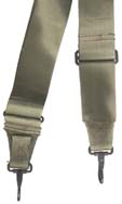
RT-1113/PRC-685820-01-079-9260 Fig 1 4 80058 705561-803 Carrying pouch 8465-01-152-1157 37695 349924-1 Carrying Harness Sling 8465-01-157-1157 37695 348814-2 Lanyard 5985-00-933-2454 Fig 1 2 80063 SM-B-522304 Short Antenna 5985-01-096-9396 Fig 1 1 37695 914161-803 Alignment Tool 5820-01-096-9410 37695 808234-1 28" Long tape meas Antenna AT-892/PRC-25 (no gooseneck) 5820-00-889-3803 Fig 1 4 37695 Battery Spacer Fig 1 3 37695 347344-1 ID Plate Fig 1 5 155035 1A1 Frame & Panel assy 5820-01-094-6523 Fig 2 1 37695 917327-803 1A6 Converter module 5820-01-094-1309 Fig 2 2 37695 917828-803 1A3 - Filter/IF module 5820-01-094-9650 Fig 2 3 37695 917829-803 1A2 - IF/AF module 5820-01-094-9650 Fig 2 4 37695 917830-803 1A9 - Synthesizer module 5820-01-094-1311 Fig 2 10 37695 917831-803 1A4 - Transmitter module 5820-01-094-6545 Fig 2 5 37695 917832-803 1A7 - VCO module 5820-01-094-1312 Fig 2 8 37695 917833-803 1A8 - Modulator/Mixer module 5820-01-094-1313 Fig 2 11 37695 917834-803 1A5 - Ant Coupler module 5820-01-094-1314 Fig 2 6 37695 919800-803 1A10 module cover Fig 2 7 37695 918267-803 1A11 Battery Housing
Fig 2 9 37695 914153-803 Antenna Connector Adapter with BNC(f) 37695 914598-801 Handset 5965-00-043-3463 80058 H-250/U BA-5588/U Battery Dry Lithium/SO2
replaced by BB-3886135-01-088-2708
6135-01-094-6536Fig 2
80058 BA-5588/U BA-1588/U Battery, Mercury 6135-01-088-2708 BB-588/U Battery, NiCad including housing 6140-01-091-1536
6140-01-241-2295
67237Simple battery Charger Single Station Battery Charger 37695 565604-801 Five Station Battery Charger 37695 706841-801 Bren-Tronics model BB-388A/U 6140-01-419-8190 AP-388/U Battery to Charger adapter (holds 2 batt) 5940-01-427-8601 BA-715 for only the PRC-68,-68A & 68B? PP-8444/U, Universal Portable Charger (UPC) costs $562.52 new
TM 11-6130-489-13&P (075017.pdf) is Restricted on ETM6130-01-427-9110 Silicon Compound, 2 oz 6850-00-177-5094 Lint Free Cloth, yard 7920-00-924-5700 TSEC/KYV-2A Secure Voice Module SVM 5810-01-160-4999
PCG-68 - Programmable Code Generator 37695 707177-802 CSD-68 fill gun (Code Source Device?) AN/GRM-114A Test Set
This is an IFR Communications Service Monitor Model 1000S and appears to have no PRC-xxx customization TM 11-6625-3016-14 (051046.pdf) and others are on line at ETM6625-01-144-4486 Vehicular mount/amplifier OF-185 5820-01-301-6301 Tool Kit TK-101/G 5180-00-064-6178 TS-3951/PRM-34 6225-01-094-5646 TS-3354 6625-01-091-3157 OE-254()/GRC Antenna Group 30 to 88 MHz 5985-01-063-1574 RC-292 antenna:
30-36.5, 36.5-50.5 or 50.5-79.95 MHz (not 80 - 88)H-250/U Handset 5965-00-043-3463 5965-01-247-4723 H-138/U Handset 5965-00-892-0972 H-189/GR Handset 5965-00-069-8886 Ear Transducer (ear mic)
Earphone Transducer (EM-200)
5966-01-187-3079?37695 588088-1
8?2969-80?H-157 AIC modified
Adapterno NSN
no NSN37695
815237-801Vehicular Adapter OF-185/PRC
30 -88 or 130 - 174 MHz depending on amp/fil5820-01-301-6301 901602-801 Diplexer, VHF, CU-2194/URC
limited upper freq of 76 MHz
Radio ports are DC open - not good with PRC-xx51859 755115A0000 Mofified Radio Shack 19-345 Simplex Repeater Controller Silicon Grease 6850-00-177-5094 68BA Battery Adapter na na na na na 68AA Antenna Adapter na na na na na 51859
SIGNAL TECHNOLOGY CORP (formerly Eaton microwave products div, formerly Addition Labs?)
CALIFORNIA OPN
975 BENECIA AVE
SUNNYVALE, CA 94086
7.1 Manuals & Literature
TM 11-5820-882-10-HR (047222.pdf) - Hand Receipt, PRC-68
TM 11-5820-882-23P (050400.pdf) - Technical Manual -23P
TM 11-5820-882-23 (= Marine TM 06827A-23/2) (047728.pdf) Technical Manual, Org & Dir Sup MaintIncludes schematic diagrams and theory of operation. This manual has information on how to program the 10 channels.Magnavox Presales sheet for Ancillaries Cables - showing the cloning and repeater (retransmission) calbes with no bumps, just cables.
Table 2-2 lists all possible channel settings and markes with a "*" those channels that might have degraded performance (probably based on spurs).7.2 Web Links
AN/PRC-68 Legacy by Alan D. Tasker, WA1NYR
PRC Data series by Dennis Starks
U.S. Military Portable Radios by By Alan Tasker, WA1NYR
Collecting Military Radios by Ralph Hogan WB4TUR
The Boneyard Radio Price Guide -
The PRC-25 Story by Dennis Starks
PRC-68-B by megaman
AN/PRC-126, Radio Set at Fort Monmouth
Non Tactical Portables at Army Radios web site
Communications Security and Related Equipment by Frederick W. Chesson -
Additional Comments by Dennis Starks on the Army Radio web page -
BB-388A/U, PP-8444A/U Charger, BA-5588U, 1588U, BB-588U
Datron World Communications MT1060MM 35 W RF booster amplifier, power conditioner, and power supply.
Audio Connectors & Cloning - Fill - Retransmission -
Military Radio Specifications - Radio Set AN/PRC-126 (RT-1547) -
Military Image Files - just a small gif image
*Crossing Linear Danger Areas* - how PRC-126 is deployed in a Squad
Soldiers of Fortune Ltd. - U.S. surplus equipment donated to the Bosnian mission include: 732 AN/PRC-126 handheld radios plus batteries, 1,600 AN/PRC-77 manpack radios with batteries
Ranger Training Brigade - Ranger Handbook TOC - Chapter Seven Communications - some operation and maintenance info
Center for Army Lessons Learned - Communications Equipment - "AN/PRC-126 Squad Radio worked well, especially in MOUT. Minor criticisms noted the audio signal for low battery and other functions which jeopardized position security and the need for an ear piece and whisper mike." - In Praise of Checkpoints - Squad use of PRC-126 and reporting check points - How to Turn Company Morters into a Combat Multiplier - Other small element leaders cannot quickly talk to the mortars without first finding a PRC-119. NOTE: Most squads carry the PRC-126, which does not frequency hop, and is not secure (? what about the SVM?, Brooke comment). This also lengthens mortar section response time.
Physics of Failure - AMXSY-LA UNCLASSIFIED 12 FEB 97 - Re-designs of ICAM, AN/PRC-126 and ARC-210 radios underway
Tobyhanna - Tactical Radio Division - Communications Security (COMSEC) Depot Opertions - Other INFOSEC Links -
C3 in the Maneuver Company -
"Use of non-secure radios (PRC 126/127s) is not allowed until contact with the enemy..." in search engine, but broken link
AN/PRC-117F Special Operations Forces radio has applications for digital divisions and beyond -
ALOG NEWS -Fort Bragg has established a central drop-off point for its 18 units that require repair support for their AN/PRC-126 handheld radios. Fort Bragg mails the radio components to Tobyhanna Army Depot, Pennsylvania, where they are repaired and mailed back to Fort Bragg. This system replaces the former practice of sending the radios through the regular supply system and cuts days off the turn-around time. The program began with the repair of circuit cards but has expanded to include other omponents, such as the PRC-126's frames and panels and its frequency synthesizer modules. Previously, these modules were thrown away rather than repaired.LRC Y2K Spreadsheet - the PRC-126 is Y2K compliant, it does not have a clock
Oral History Interview JCIT 0811LT JOHNSON: Well, get back to training, but again that's one thing that we didn't want to lose; lessons that we had learned. We took time and really wrote up a pretty substantial AAR which we got here. I have already noticed some ... one change come out of it. It was very minor point to put on the tape, but on the PRC-126 the little display panel is in green plastic. The idea behind that is so that it reduces the amount of light when you hit the display light at night. But in actuality, it makes it very hard to read any time either during the day or night. We have been trying to do this for awhile, but we just included in this after action report and that's what brought about the changes and everything. Now there is just clear plastic.Special Operations Forces Posture Statement 2000 - Appendix C Key Programs & Systems - ** Improved weight/size and power consumption by replacing numerous multi-frequency/banded, hand-held radios currently used (i.e., AN/PRC-68, AN/PRC-126, MX-300, MX-300S, and MZ-300R) with one full range/band radio
Specialty Defense Systems - Ranger Assault Carrying Kit (RACK) -7.3 NIIN Text File (NIIN.txt)
This is a file that can be used for searching the DRMS (Defense Reutilization and Marketing Service). It contains all of the NIIN numbers listed above in the Parts List.7.4 Related Radios
The following radios are all in the PRC-68 family and use the same battery and secure voice module. They all use the H-250 handset.
A power increase of 6 dB (1 "S" unit or 4 times) the wattage) is just noticable by the human ear, so a radio would need 4 Watts to just be louder than the PRC-68. Why would you want ot carry the weight of a PRC-25 or PRC-77 if you could have a PRC-126? Adding the OF-185/PRC
They have a similar physical appearance.- PRC-68 - 30 - 79.95 MHz
- PRC-68A - 30 -79.975 MHz
- PRC-68B - 30 - 87.975 or 130 - 173.9875 MHz by changing the RF/IF module
- PRC-126 - 30 - 87.975 MHz
- PRC-128 - 30 - 87.975 or 130 - 173.9875 MHz by changing the RF/IF module
- PRC-136 - 130 - 173.9875 MHz
amplifier results in a much more powerful vehicle mounted radio set.
8.1AUDIO J5 Pins
J5-A (Ground)
Back to Brooke's Products for Sale, Audio Connectors & Cloning - Fill - Retransmission, Squad Radio, Military Information, Electronics, Home pageJ5-B (Earpiece)
Speaker Muting
The PRC-68 J5-B (audio out) is near+5 VDC when the radio is quiet and the DC level jumps to about +6.2 VDC when the squelch opens. The reason is to sense if an external earpiece or speaker is present. If so the speaker is muted.
Remember that the 1/4" phone plug does this mechanically, but with the MIL-C-55116 connectors there is no mechanical switching possible.An AC coupled audio accessory with a high impedance DC voltage controled comparator could be used to detect when the squelch opens and be used for retransmission PTT control.
Pull Down Resistor Value for SPKR Mute
(For the PRC-68 SPKR mute requires less than 3.3 K Ohms? this may be a function of battery voltage?)The AC output impedance of the PRC-68 is about 50 Ohms. The radio will put out just under 100 mW of audio.
J5-C (Push To Talk)
This has the same fuctions as the PTT switch on the radio.J5-D (Microphone Hot)
From J5-D to ground is ???150 Ohms. This matches the impedance of the H-250 handset.
This also is what provides the pull down resistance to cause the FILL mode to activate when an H-350 handset is connected.J5-E (DC Power)
To use external power set the OFF-ON-SQUELCH DIS switch in the OFF position. That turns off the battery and connects to the External power.
page created 29 Oct. 2000.