Bowman
H4855 & H4855U
AN/PRC-343
Personal Role Radio PRR
Integrated Intra Squad Radio IISR
© Brooke Clarke 2006 - 2012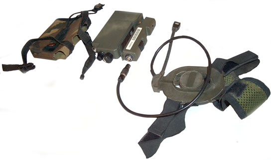 |
| Pouch, Radio, Antenna, 1
button PTT, Headset |
|
| Pouch, Radio, Antenna, 1
button PTT, Headset |
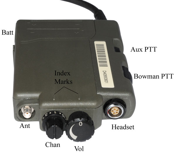 |
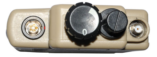
Chan: 16 Positions (1
shown) Off/Vol: 5 Positions (Off shown) Ant: SMAf recessed. Headset: LEMO 5 pin Bowman PTT for this radio Aux PTT: for Combat Radio (CR) |
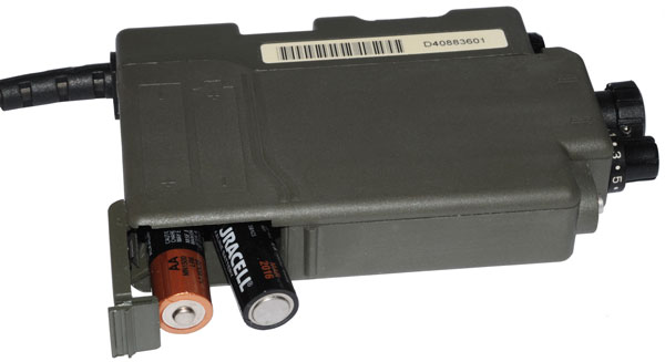 |
1. OFF/Vol to Off 2. Connect Headset Push headset connector to seat it 3.Insert 2 AA batteries (observe polarity markings) 4. Check that Chan is on proper channel 5. connect antenna 6. Switch Vol control on to medium position |
 |
The work PROGRAM on the
wireless PTT is positioned over the bump where the reed switch is located in the PTT module. 1. Start with the OFF/Vol control at OFF. 2. Switch Vol on to a medium volume position. Ascending Tones are heard. 3. Press and hold wireless PTT until ascending tones are heard a second time. 4. Release wireless PTT. 5. Note: decending tones heard of affiliating did not work. If so, repeat steps 1 to 4. |
|
1. Switch Off. 2. Switch On to medium volume. 3. Without pressing wireless PTT, remove and return wireless PTT to and from radio 5 times within 5 seconds of turning on radio. Ascending tones heard. First de-affiliating then Affiliating WPTT. http://www.youtube.com/watch?v=FzbhupKswmk |
| |
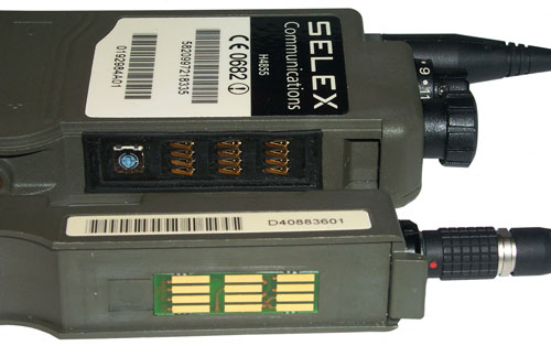
Instead of just using a common PTT switch there are a number of innovative options. The PTT module screws onto the narrow left side of the radio making contact with a 3x4 (12 ) contacts array. There are a number of tone signals that let the radio operator know some key status situations. These can be turned off by holding PTT while turning on the radio. See above for the tones.
When the PTT slice is removed from the radio the 12 electrical connections that are exposed go directly to the internal electronics.
If anti static precautions are not used there is a chance that the radio will be permanently damaged.
See my YouTube video H4855 Wireless PTT.
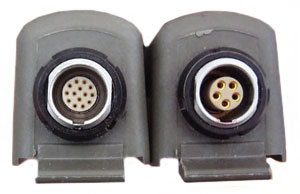 |
14 pin LEMO Dual PTT vs.
Single or Dual PTT |
Bowman Dual PTT module
with 14 pin Plug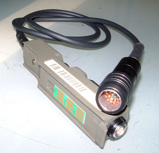 |
marked: 5930998401824 i.e. NSN: 5930-99-840-1824 D3701882B1 Plug mates with: Thomson-CSF (Thales) 9100 handheld and 9200 manpack VHF radios Green - Mic + - Pin A (on clansman connector) White - Mic - - Pin B Red - +24 VDC (used in clansman radio system and therefore N/A in H4855) - Pin C Yellow - Speaker + - Pin D Blue - Ground - Pin E Black - PTT - Pin F info from Lennart who is in Hi Lennart Sweden |
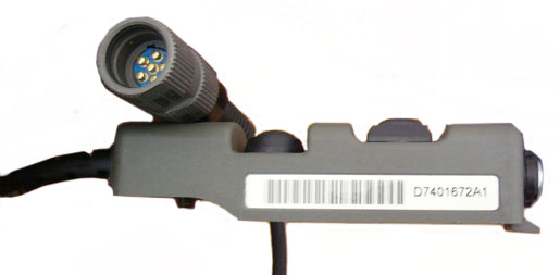 |
D7401672A1 6 pins in U-229 type connector |
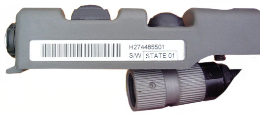 |
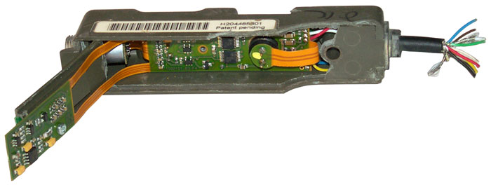
H274485501 S/W STATE 01 |
 |
Maybe for linking a GPS
to the radio? |
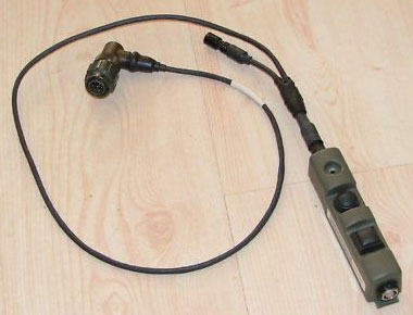
| VPPT Vehicle PRR PTT module | |
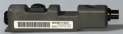 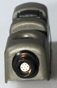 |
Vehicle PRR PTT module The top LEMO is the standard audio conn. The bottom LEMO is smaller and is probably for DC power to the radio. No batteries are used in the radio. S5002031A1 5930991319201 (NSN 5930-99-131-9201) There is a GPS add-on for sale from eBay seller east_sector titled: GPS BEACON NAVIGATION MODULE THALES PERSONAL RADIO EZPRR That appears to plug into this PTT module. The radio shown in the eBay ad is marked: H-174-4855-ELSA |
| NSN |
Prod # |
Description | ||||||||||||||||
5820-99-721-8335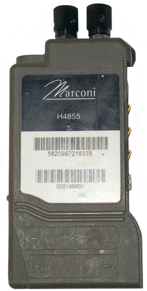 |
P21050000 |
PRR Body (Green) Complete –
English The PRR body is complete with an antenna and
an English user card. Must be used with single or dual
push-to-talk (PTT) switch assembly. Requires two AA
batteries (included). Infantry use (500m range) |
||||||||||||||||
5820-99-739-4033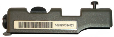 |
P08130000 |
Single PTT Switch Assembly
(Green) The single PTT switch assembly is for use with the
PRR body. |
||||||||||||||||
5820-99-342-4097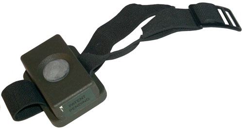 |
P08120000 |
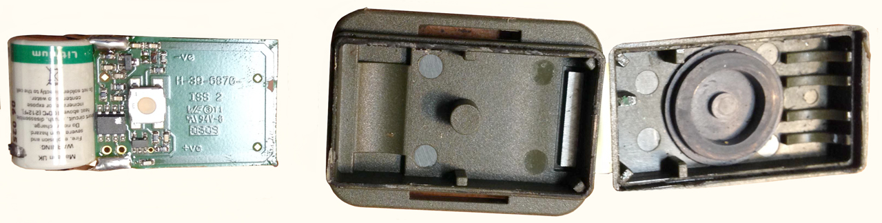
Remote Wireless PTT
(Green)The wireless PTT remotely operates the PRR.
Supplied with a black adjustable strap and buckle. Uses LST14250 battery with tabs. Photos supplied by Dick. Opened using chisel to separate case halves.
|
||||||||||||||||
| WPTT Mk II Dual DICL NSN 5895-99-213-4258 (aka: P08230200)
|
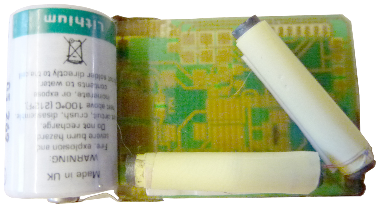
If you know anything about this let me know. Atmel 90S23213 8-bit microcontroller (uC) CSB455J muRata 455 kHz resonator I expect that it's programmed on the board hence the 2x3 group of pads plus other pads for power, ground and ??? There are a couple of loopstick antennas, but there's no other IC that could be associated with them, so some direct connection to the uC? The case is marked: PROGRAM P08230200 100495 Where is the magnet to trigger radio affiliation? ans. under the word "PROGRAM" like the other WPTT units. |
|||||||||||||||||
5820-99-127-2911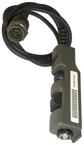 |
? |
Dual PTT with 7 pin
Clansman cable connector The
mode / SQ pin . On UK MOD sets that have
been modified (1) .
on a dual ptt you get a hi/low tone on TX in your headphone that repeats every five seconds ... it
can be stopped by taking the mode pin the ground via
a 10k resistor.
This
only happens on a later set and with a dual ptt
|
||||||||||||||||
| 5820-01-531-1752 | AN/PRC-343 personal role
radio set with: Radio P21250100 5820-99-721-8355 Single PTT P08130000 5820-99-739-4033 Wireless PTT P08120000 5820-99-342-4097 Daylight Headset P0814490008 5965-01-533-3341 Boom Mike Adapter P07120000 NSN? Carry Pouch P30180100 5895-99-991-3095 |
|||||||||||||||||
| 5820-01-531-1758
(see DPRR below) |
P21050041 | AN/PRC-343 personal role
radio set with: Radio P210501000 5820-99-721-8335 Dual PTT P08140341 5820-99-666-0452 (<-???, see below) Wireless PTT P08120000 5820-99-342-4097 Daylight Headset P09255+0009 NSN??? Boom Mike Adapter P07120000 NSN? Carry Pouch P30180100 5895-99-991-3095 |
||||||||||||||||
| ? |
? |
Single PTT with
(detachable?) PDA cable |
||||||||||||||||
| 5820-99-280-7276 |
P14360408 |
CT/Light Patrol Headset
(Green) – Noise-Canceling (NC) Electret Microphone The
vented, single-sided headset has an NC Electret microphone
fitted to a flexible boom arm. Fitted with an adjustable
headband, the headset can be worn underneath most passive
ear defenders. |
||||||||||||||||
5965-01-533-3341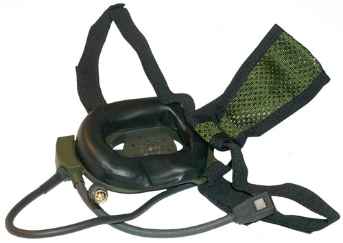 |
P14490008 |
CT/Light Patrol Headset (Green) – Noise-Canceling (NC) Electret Microphone The vented, single-sided headset has an NC Electret microphone fitted to a flexible boom arm. Fitted with an adjustable headband, the headset can be worn underneath most passive ear defenders and balistics helmets. | ||||||||||||||||
5965-99-664-9722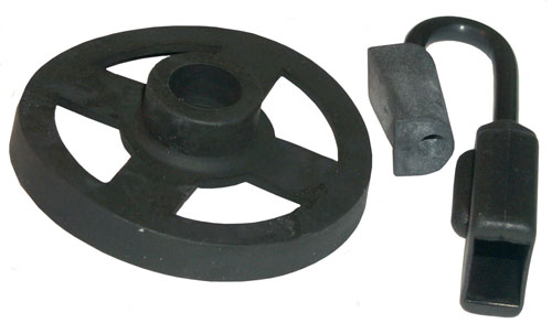 |
P07100000 |
Nuclear, Biological, or Chemical (NBC) Boom Microphone Adapter The adapter is for use with most Davies headset models. One end fits over theheadset’s boom microphone and the other end plugs into the respirator’s speech module. See patent 7493899 below | ||||||||||||||||
5820-99-425-3999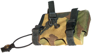 |
C410114 |
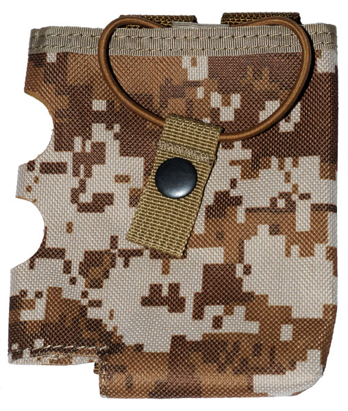
Carry Pouch (Green) –
United Kingdom (UK) Pattern Disruptive Pattern Material
(DPM) The PRR fits inside a heavy-duty polyurethane,
textured nylon pouch that attaches to webbing and helps
protect the PRR from harsh conditions/impact. |
||||||||||||||||
5895-99-991-3095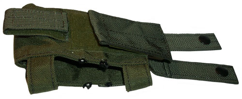 |
Carry Pouch (Green) - U.S.
Molle |
|||||||||||||||||
5985-99-664-9730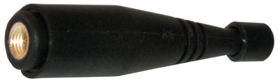 |
Antenna |
|||||||||||||||||
5820-01-533-3406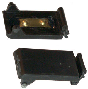 |
Battery Door The two doors shown are aftermarket made by Dragondark. |
|||||||||||||||||
| 5820-01-533-3652 |
Strap & Buckle for
Wireless PTT |
|||||||||||||||||
5820-99-666-0452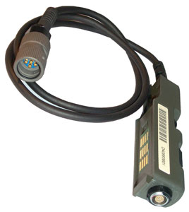 |
| Contact |
Function |
| 1 |
Mircrphone In |
| 2 |
? |
| 3 |
Speaker Out |
| 4 |
+Vout |
| 5 |
Ground |
| 6 |
Push To Talk |
| 7 |
Busy pips (active low) |
| 8 |
? |
| 9 |
Reset (Active low) |
| 10 |
RxD (CMOS 3V URAT In) |
| 11 |
TxD (CMOS 3V URAT Out) |
| 12 |
Single/Dual PTT select
(0=Single, 1=Dual) or (Open Squelch / PTT) |
| 1 |
2 |
3 |
4 |
5 |
6 |
7 |
8 |
9 |
10 |
11 |
12 |
| Mike |
PTT |
Spkr |
+Vout |
Gnd |
PTT | RxD |
TxD |
PTTsel |
| B R-> V |
1 M |
2 P |
3 S |
4 |
5 G |
6 |
7 |
8 |
9 |
10 |
11 |
12 |
| 1 mike |
x |
|||||||||||
| 2 PTT |
x |
x |
||||||||||
| 3 Spkr |
x |
x |
x |
|||||||||
| 4 |
x |
x |
x |
x |
||||||||
| 5 Gnd |
x |
x |
x |
x |
x |
.044 |
||||||
| 6 |
x |
x |
x |
x |
x |
x |
.044 |
|||||
| 7 |
x |
x |
x |
x |
x |
x |
x |
.044 |
||||
| 8 |
x |
x |
x |
x |
x |
x |
x |
x |
.044 |
|||
| 9 |
x |
x |
x |
x |
x |
x |
x |
x |
x |
|||
| 10 |
x |
x |
x |
x |
x |
x |
x |
x |
x |
x |
||
| 11 |
x |
x |
x |
x |
x |
x |
x |
x |
x |
x |
x |
|
| 12 |
x |
x |
x |
x |
x |
x |
x |
x |
x |
x |
x |
x |
| B R-> V |
1 Mik |
2 PTT |
3 Spk |
4 |
5 Gnd Bat - |
6 |
7 |
8 |
9 |
10 |
11 |
12 |
| 1 Mike |
X |
.040 |
0.3 |
cap |
||||||||
| 2 PTT |
X |
X |
.054 |
.051. |
.050 |
.051 |
.052 |
.05 |
.05 |
cap |
||
| 3 Spkr |
X |
X |
X |
2.2 |
.77 |
2.0 |
1.96 |
cap |
1.9. |
1.8 |
1.8 |
cap |
| 4 |
X |
X |
X |
X |
-2.968 |
-.01 |
-2.915 |
-2.967 |
||||
| 5 Bat- GND |
X |
X |
X |
X |
X |
+2.594 | .05 |
+2.963 |
+2.938 |
+2.963 |
||
| 6 |
X |
X |
X |
X |
X |
X |
-.006 |
-2.907 |
-2.959 |
|||
| 7 |
X |
X |
X |
X |
X |
X |
X |
-2.901 |
||||
| 8 |
X |
X |
X |
X |
X |
X |
X |
X |
+2.910 |
+2.885 |
+2.91 |
-.048 |
| 9 |
X |
X |
X |
X |
X |
X |
X |
X |
X |
-2.962 |
||
| 10 |
X |
X |
X |
X |
X |
X |
X |
X |
X |
X |
-2.936 |
|
| 11 |
X |
X |
X |
X |
X |
X |
X |
X |
X |
X |
X |
-2.962 |
| 12 |
X |
X |
X |
X |
X |
X |
X |
X |
X |
X |
X |
X |
| B R-> V |
1 Mike |
2 Gnd |
3 Gnd |
4 Spkr |
5 ? |
| 1 Mike |
0 |
||||
| 2 PTT |
|||||
| 3 Spkr |
0 | ||||
| 4 |
|||||
| 5
Gnd |
0 | 0 |
|||
| 6 |
|||||
| 7 |
|||||
| 8 |
|||||
| 9 |
|||||
| 10 |
|||||
| 11 |
|||||
| 12 |
|
|
From an Airsoft
web page, but I think they have it close but there's
more to it. For example the Blue wire seems to be
the true ground. Black: Gnd (PTT) PTT: White (PTT) Speaker+: Orange Speaker-: Blue Mike: Green Mike (power?): Red |
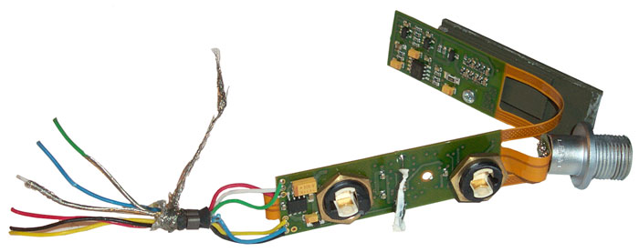 |
The green & white wires
are shielded. The white RTV is surrounding the reed switch that's under the hump between the two PTT buttons. There are 12 SMT caps at the top right of the top PCB (next to the notch in the flex circuit) and the center ends of all of them connect to the blue (gnd) wire. |
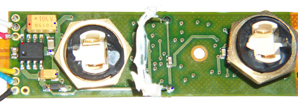 |
Blue dots are connected to
the blue PTT cord wire (looks like ground). Red dot
connected to red PTT cord wire. IC is marked LM293 |
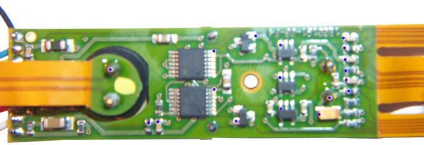 |
Blue dots are connected to
the blue PTT cord wire (looks like ground). Top IC is marked HC02A Bottom IC is marked HC14A The three 5 lead SOT-23 packages are marked "AAA". |
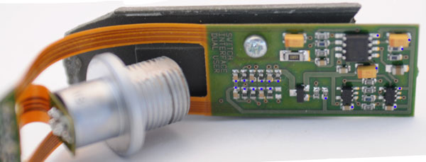 |
Blue dots are connected to
the blue PTT cord wire (looks like ground). The IC on the back of the 12 contact PCB is marked MAX4167. |
| 2nd Radio Cable
(PCB order) |
Radio I/F |
|||
| Black | ? |
|||
| Blue |
6, 8 |
DC Gnd
& Speaker Return |
||
| Yellow
(orange) |
Speaker
Audio |
|||
| Red | Mike DC
power |
|||
| White (shielded) | 2nd
Radio PTT |
|||
| Green (shielded) | Mike
Audio |
|||
| 3 |
top (Radio) PTT |
|
|
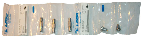
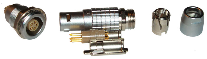 EGG.1B.305.CLL FGG.1B.305.CLAD62 |
 |
The H4855U has a red mark
on the LEMO connector and I'm assuming it's pin # 1. |
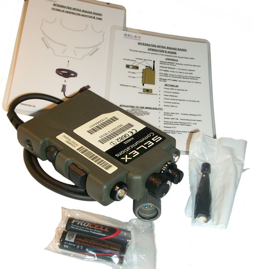 |
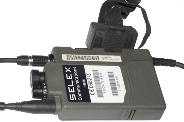
SELEX Radio Set
5820-01-531-1758 Radio 5820-99-721-8335 Dual PTT (H204485601, D40883601) w/GC329 connector attached, Antenna, two AA cells, card marked "Integrated Squad Radio Operator's Guide card marked Integrated Intra Squad Radio Fitting of Reppirator Adaptor & Tube |
|
Headset (P1449008)
NSN 5965-01-533-3341 |
Wireless PTT |
Remote PTT
(5820-99-342-4097, P0812000) (bag marked use by
01/01/17 |
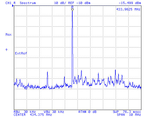 |
Bowman Wireless PTT
spectrum HP 4395A 433 MHz Tx frequency |
|
Universal Carry Pouch - ALICE or Molle |
|
Gas Mask Adapter |
 Dual Personal Role Radio Internal Channel Switch set to Channel 0 |
H4855U Set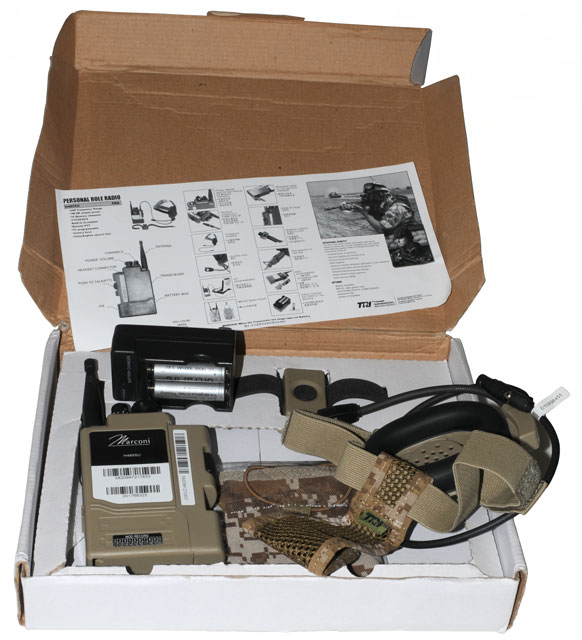 |
||||||||||||||||||||||||||
H4855U Max Hold Spectrum
from chan 1 and chan 16 (made with HP
4395A)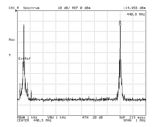 |
The display spectrum
correlates with the data sheet that shows 440.050 for Chan
1 and 440.800 for chan 16 (i.e. 50 kHz chan
spacing). This was done with the two DIP switched
off. |
|||||||||||||||||||||||||
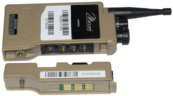 |
H4588U Radio 5820-99-721-7655 Mod Record: 1, 4, 16 Single PTT 5820-99-127-0957 Have not tested to see if it works with a real radio, but suspect that it will. |
|||||||||||||||||||||||||
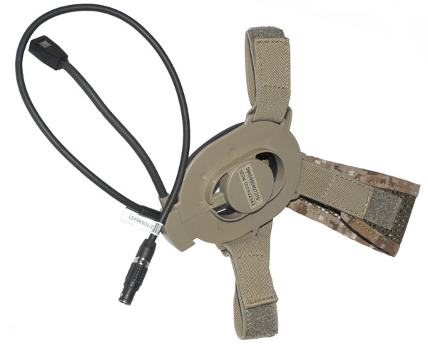 |
Headset 5965-99-280-7276 This has a real LEMO connector and is form, fit and function interchangable with the real headset. |
|||||||||||||||||||||||||
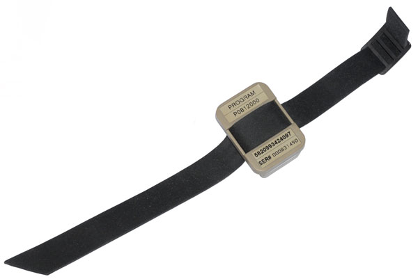 |
Wireless PTT 5820-99-342-4097 DIP switch #2 (under the single PTT) turns on or off the wireless PTT. There does not seem to be an affiliate function like on the 2.4 Ghz radios. But PROGRAM appears on the unit, strange. Works on a different frequency than the real wireless PTT and so will NOT work with a real radio. |
|||||||||||||||||||||||||
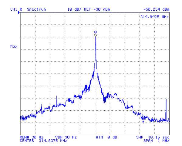 |
The wireless PTT operates at 315 Mhz not the 433 MHz that's used for the 2.4 Ghz radios. That's probably to seperate the PTT frequency from the radio frequency. | |||||||||||||||||||||||||
 |
||||||||||||||||||||||||||
Set
#2 came without batteries and charger so can not be
powered up until I get a couple of the special batteries
(3.6 V 900 hAh).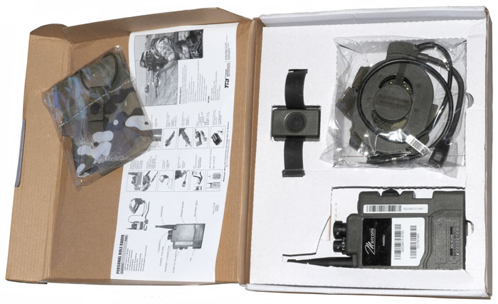 |
||||||||||||||||||||||||||
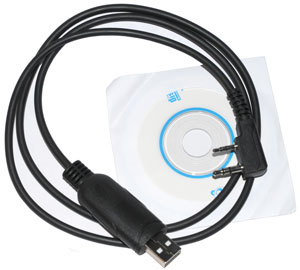 |
Kenwood stock programming
cable The hope is to modify this cable to work with the H4855U. |
|||||||||||||||||||||||||
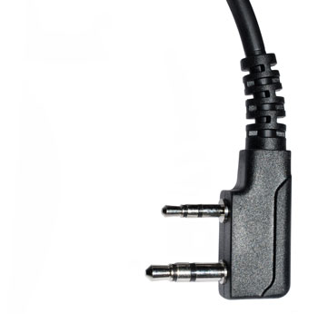 |
Kenwood stock programming
cable Plug The hope is to identify the function of the plug contacts then after cutting the plugs off link the function to wire colors. |
|||||||||||||||||||||||||
Kenwood Interface |
Kenwood
TH-F6 Data Interface pinout from the owner's manual
page 45. It's probable that the data interface for programming is the same. The programming cable only has three wires: Red, Black and White. This is my best guess asto how to make a programming cable.
Note: there are pull up resistors to +3.5 V on the DCD and PTT lines. Myabe in the 1k to 3.3k Ohm range. The wiring is based on cutting a cable sold on eBay as a Kenwood programming cable, i.e. that's why the wire color and DCD, Gnd & PTT connections. |
|||||||||||||||||||||||||

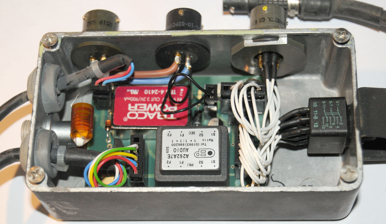 |
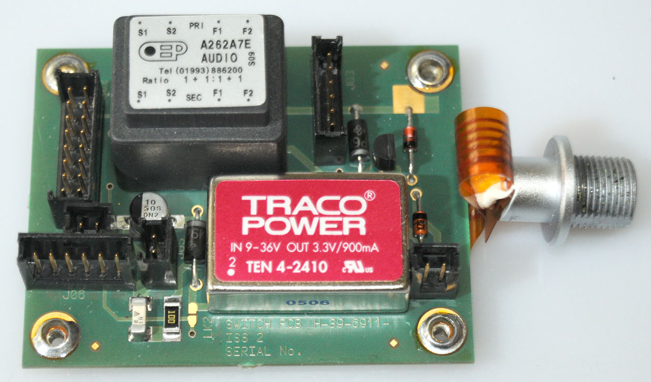
The red rectangular
component is a power supply. marked: Traco Power In: 9-36 V Out: 3.3V 900 ma Ten 4-2410 The silver rectasngular component is an Eisen audio transformer marked: A262A7E Audio Tel (01993)886200 The box is a Hammond 1590-NI |
||||||||||||||||||||||||
 |
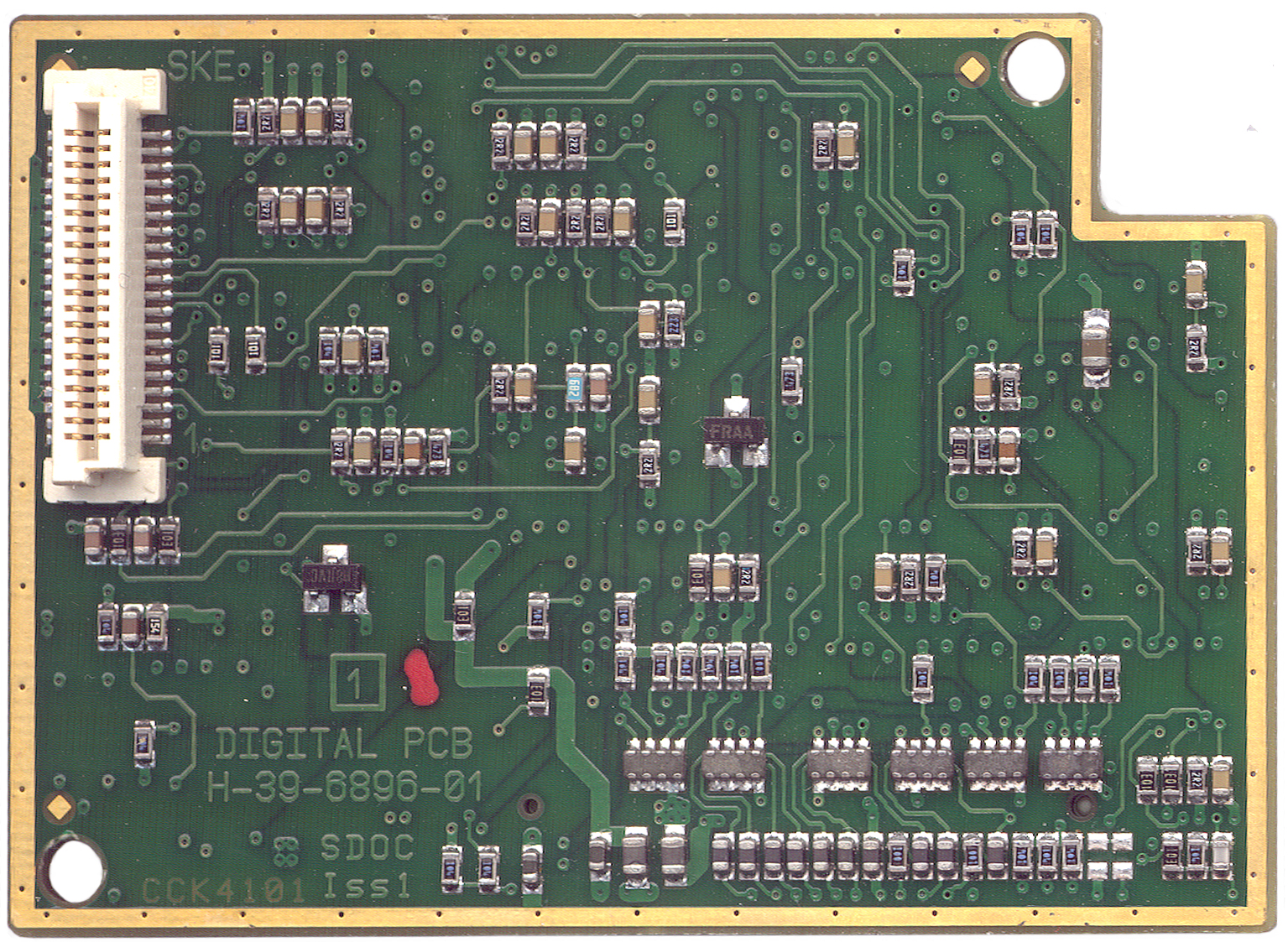
On the bottom of the PCB
there are a bunch of 1 uF caps and an 8 lead IC marked: 33171
PZGL which is a low power Op Amp |
||||||||||||||||||||||||
 |
The Traco Power module
supplies +3.3 V to power the radio. The Transformer is wired:
|
| Cable Box - end | Connector - end |
||||
| Label |
Cable
Labels |
Cable
Wires |
Conn |
Conn - Pins |
|
| CLANS/PRR |
(Other/CLANSman)/PRR |
3PDT
switch 9 white wires |
|||
| PLA |
7 male
pin cir conn (capped) |
A: B: C: D: E: F: G: lemo-2 |
GB
62GB-57A10-7PE 5 white wires |
||
| PLB |
2 male
pin conn DC Supply |
ska & DC Power | GB 62GB
51T10-2PC TCX note 1 2 pins Brown
Blue
|
A: +24V B: Gnd |
|
| SKC |
2
female scokets DC to Vehicle Radio |
DC Supply & +28V | GB
62GB56T10-2SC TCX note 1 2 sockets Brown
Blue
|
A: +24V B: Gnd |
|
| Harness Output |
HO LEMO
jack (same as on radio)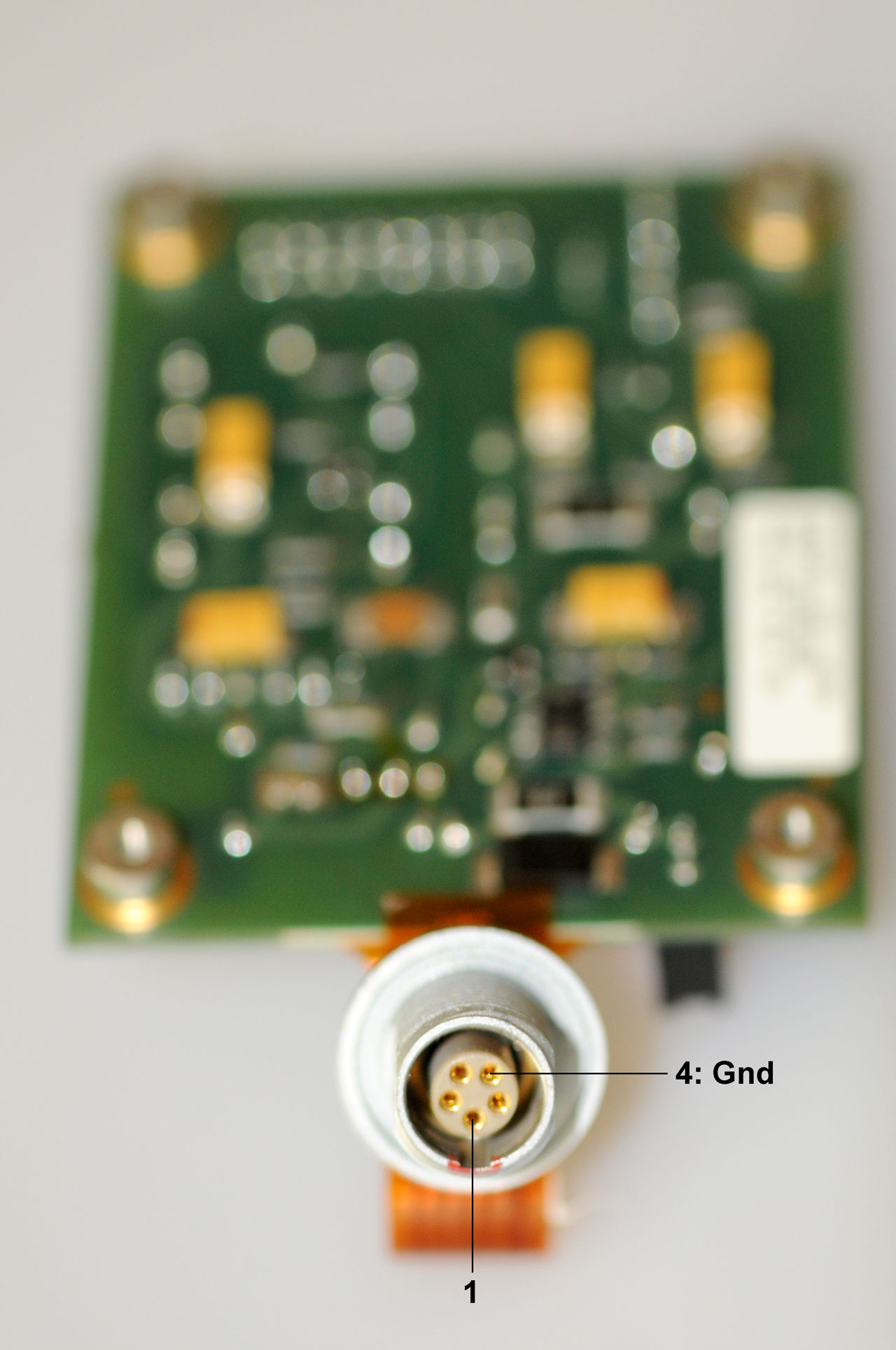 LEMO p/n: HMG.1B |
936-155/01 - harness output |
1: 2: PLA-G 3: 4: Gnd 5: |
[PU]APH
0613 62GB-56T10-07SE 7 sockets flex circuit |
A: B: C: D: E: PLA-E F: G: PLA-G |
| na |
attached
cable
- LEMO plug (radio Audio) 936-1540/01 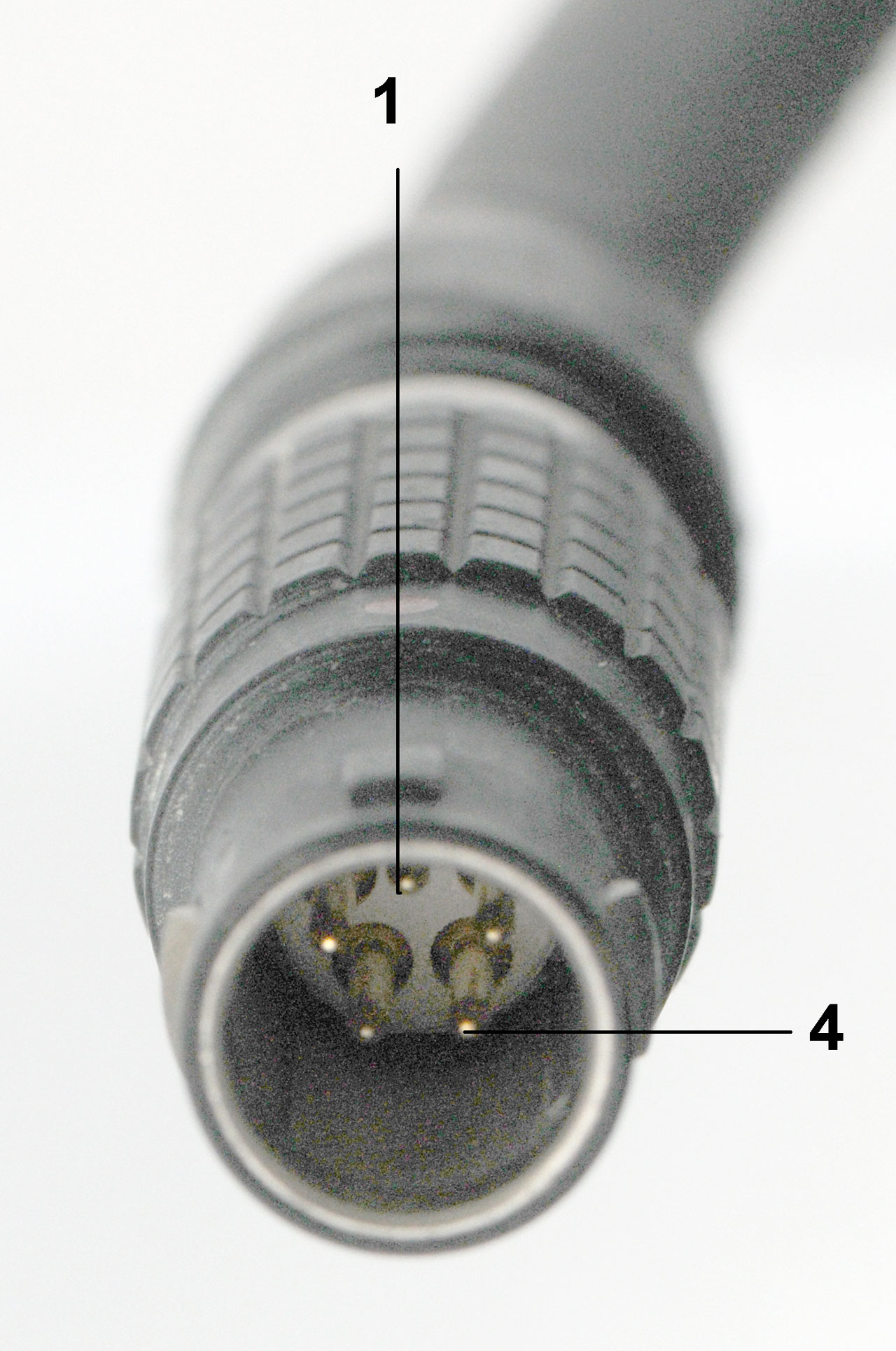 |
(red dot
on shell) red blue yellow green white black |
1 2: Gnd 3: Gnd 4: 5 6: nc |
||
| na |
attached
cable
- small 6 pin LEMO to Vech PTT module
(PS) 936-1541/01 Note 2 |
red blue |
|||
 |
 |
 |
 |
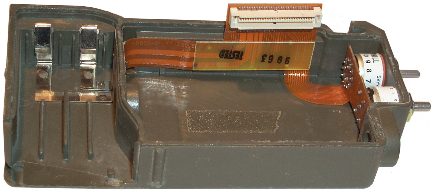
| 1. Lid
Removed |
2.
Connector lifted & Shield removed. Lines to tabs. |
3. Tabs
bent & Digital board top removed from radio |
4.
Remove SMA nut & can from chassis |
 |
 |
 |
 |
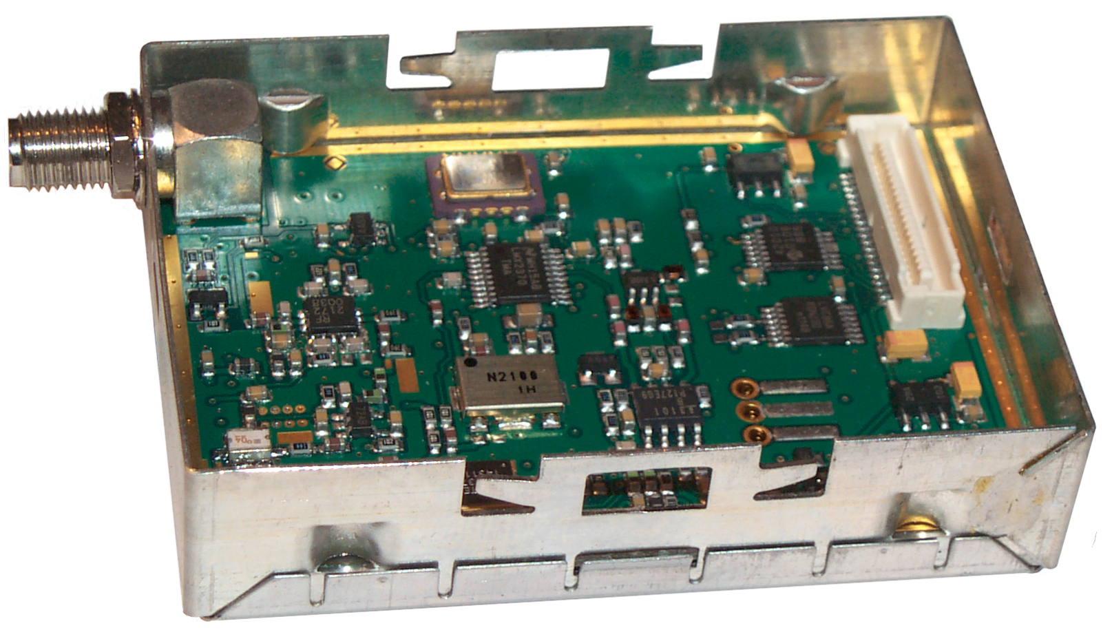
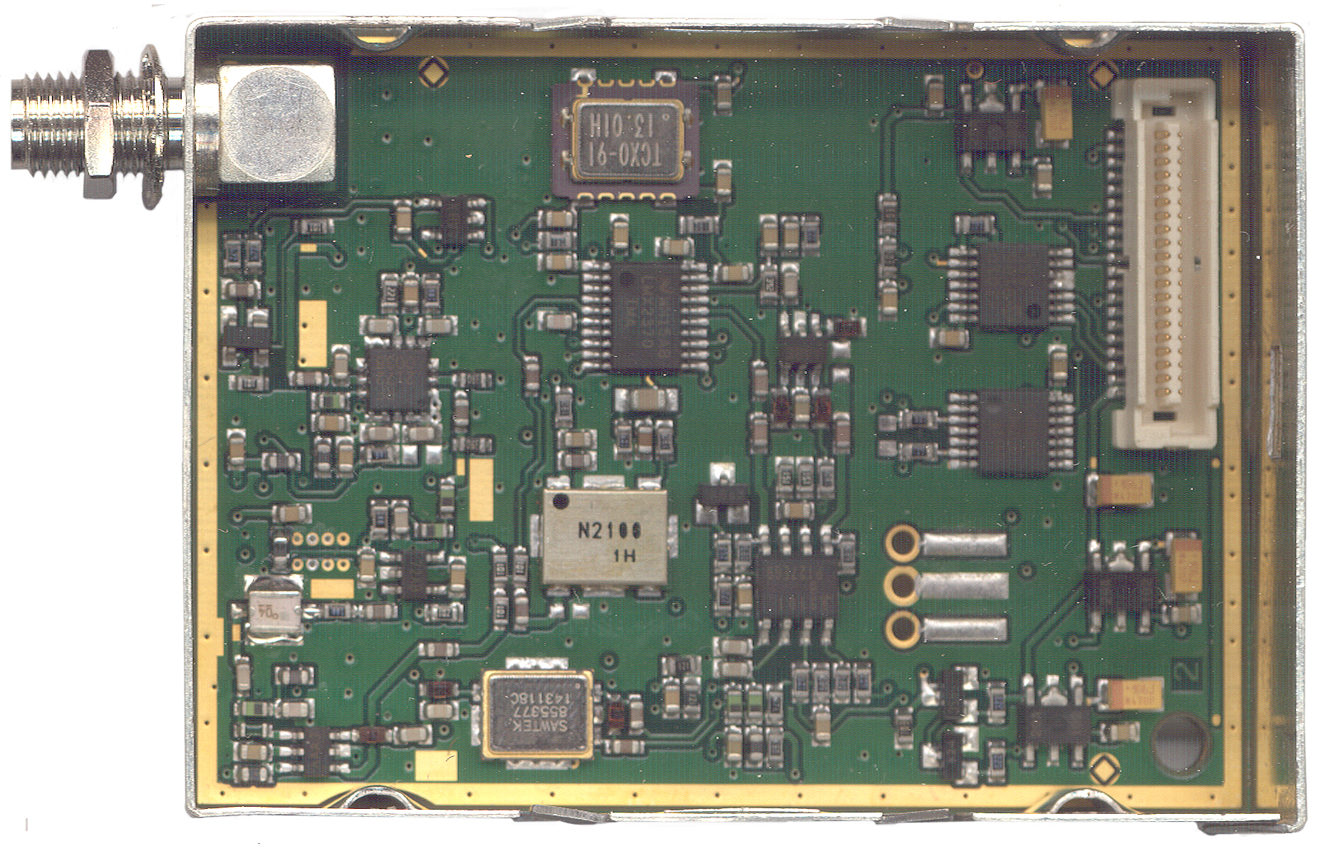
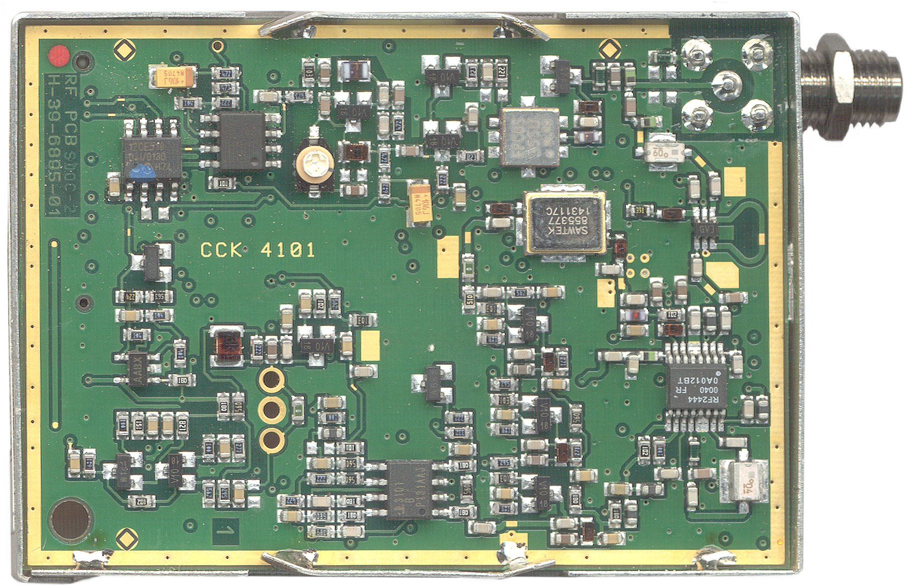
| 4. Top
of RF board |
4.
Bottom of RF board |
3.
Digital board bottom |
5. Box
& flex ckt w/ switches |
Brooke,
If anyone else asks you, the EZ PRR or H4855-ELSA will work into a standard PRR on channel 16 only. Also, the PTT module with it will not work with a WiFi PTT even though it appears to affiliate. Using a standard PTT module does allow the WiFi PTT to work.
The EZ PRR PTT module is NSN 5930-99-461-4943 and has a data port (GPS?) on the bottom.
Hope this is of interest,
Gordon