Mk 20 Mod 4 Gun-Bomb Sight
© Brooke Clarke 2018
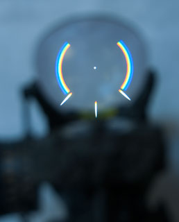
Pilot's View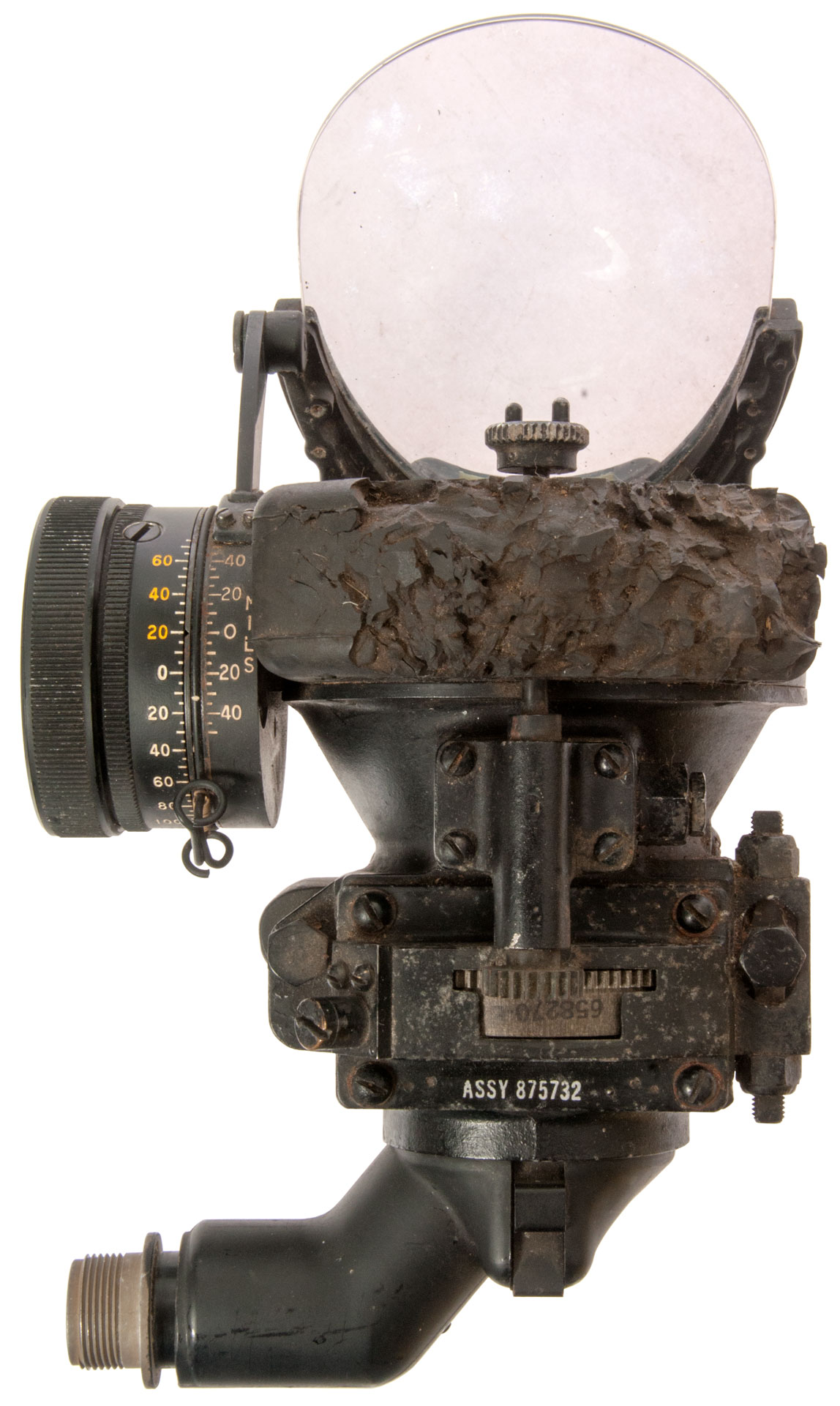 |
Image from AF
National Museum AC-47 "Spooky" Gunship 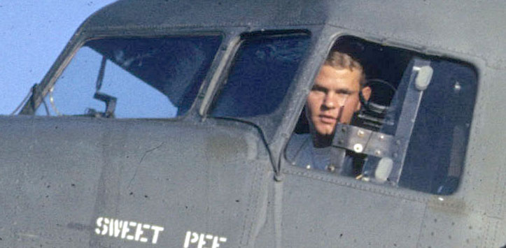 |
 |
Application
SBD Dauntless
A-1 Skyraider
AC-47 Gunship
OV-10
Optics
NC-3
N-6A Gun Sight
Mk_20_mod_4_Description
Controls and Indicators
Lamp Housing
Connector
Head - Glass Plate
Head -Optics
Reticles
Knob
Mk 20 Documents
Photos
Patents
Related
References
Links
Background
While learning about Torpedoes I discovered that their range (how far they can go on their own power) far far exceeds the range at which they can hit a ship. The company that made the Torpedo Data Computer (TDC), Ford Instrument (Wiki, Doug Coward), also made the Gun Director (GD) used on Battle Ships (Wiki). In my opinion those big guns have never hit a moving ship at anywhere near their maximum range of 35,000 yards (20 miles) (Wiki). Note the TDC and GD were there to solve the problem of a moving firing platform targeting a moving ship where the weapon takes some time to move from the firing platform to the target. The weapon is "dumb" in that it does not have any terminal guidance. So the aiming angle and the instant it should be fired must be very precise in order to hit the target.
The Nordeen bombsight never worked, it was mostly marketing hype. It was developed by the Navy, but after testing they gave up and went to dive bombing (Wiki). Horizontal bombing (Wiki) only works in the "Carpet Bombing" (Wiki) mode which results in high civilian causalities.
So, what bomb sights were used for dive bombing. They are forward facing unlike the downward looking bomb sights used for horizontal bombing.
This sight came after the NC-3 and before the Navy Mk 18 Gyro Gun Sight in my collection.
Application
Note modern warplane nomenclature uses the first letter "A" for Attack aircraft (Wiki), "B" for Bombers (Wiki), "C" for Cargo (Wiki), "E" for Electronic Warfare (Wiki), "F" for Fighters (Wiki). Here are some dive bomber sights:
SBD Dauntless
The Douglas SBD Dauntless (Wiki) used what amounts to a 3X rifle scope (Wiki) in a fixed mount at the top center of the instrument panel sticking through the windshield base.
Note you can see the bomb sight is about 2 or 3 feet long and maybe a few inches in diameter. Also the dive brakes are deployed. The most important thing to notice is that the bomb is far below the plane because a special trapeze bomb rack moved it outside the propeller disk. Since the bomb has a lower drag coefficient (Wiki) than the plane it speeds up after release and would go through the propeller if released from a conventional bomb rack on the plane's centerline. In the photo you can see that the bomb's nose is forward of the wing leading edge.
see Aircraft patents: 2386839 Bomb displacing gear & 2466980 Missile ejector for aircraft for examples of dive bomb racks.
The SBD was a very successful plane and almost 6,000 were made.
Note trapeze bomb rack
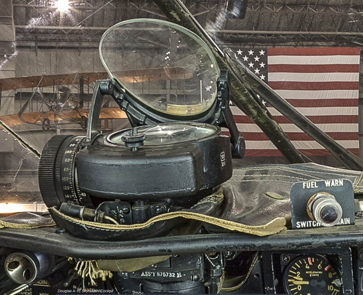
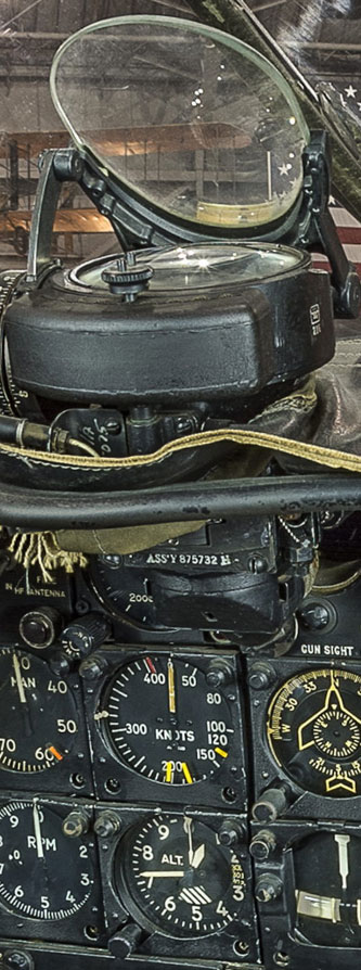
A-1 Skyraider
The Douglas A-1 Skyraider (Wiki) replaced the SBD as a dive and torpedo bomber. It used the Mk 20 Mod 4 sight for both dive bombing and it's fixed guns as well as other armament. I've found YouTube footage of VNAF (Wiki) using the A-1 in dive bombing mode, but mostly newer footage is of dropping Napalm (Wiki) in low level horizontal mode, not dive bombing.
Rockets (Wiki) are different than Missiles (Wiki) in that rockets have no guidance. The A-1 Skyraider can be armed with rockets, maybe either the standard 2-3/4" Folding-Fin Aerial Rocket (Wiki) or the 5" Zuni (Wiki). Note the Zuni has a 15 pound warhead and the 2-3/4" rocket a smaller warhead, so I don't see how they can be thought of as a replacement for iron bombs (Wiki: M117, M118, M81, M82, M83, M84, BLU-109, BLU-116) that range in size from 250 to 2,000 pounds. That raises the question is dive bombing a current thing? Note since dive bombers are slow moving they make easy targets for fighter planes, but when the U.S. is in active warfare they own the sky so that's not a problem now.
Photo from 3D image at National AF Museum
Note Instruments directly below sight:
Airspeed
Altitude
AC-47 Gunship (Wiki, Aircraft: Gunships, Ref 2)
The miniguns (Wiki) fire to the left instead of forward. So the Mk 20 Mod 4 gun sight is mounted in the left window as shown in the photo. A cargo plane is used to carry the weight of the ammunition.
3380343 Firing mechanism for high rate of fire multi-barrel automatic weapon, Robert E Chiabrandy, Douglas P Tassie, General Electric Co, 1968-04-30 -
3595128 Bolt Assembly, John P Hoyt Jr, General Electric Co, 1971-07-27 -
6742434 Machine Gun, Michael J. Dillon, 2004-06-01 -
YouTube:Dark Docs: Puff the Magic Dragon: The AC-47 "Spooky" Gunship
Aircraft Ref 47: YouTube
Image from AF National Museum
OV-10 Bronco (Wiki) (JOV-1A" and "JOV-1C)
See Air Vectors
From: http://www.aircraft-gunsights.com/reflector-sights/
"The Mark 20 Mod 0 Sight was fitted mostly to Douglas Skyknights (F3D-1 and F3D-2); the Vought F4U-5N(L) Corsair and finally Grumman F7F-3N Tigercat and F8F-2N Bearcat. The Mark 20 Mod 4 was used mostly on Douglas Skyraiders (A4D-N, AD-5, AD-5N, AD-6) but also Grumman S2F-1 and some Air Force planes (see separate page on Air Force Sights)."
Optics
There are a number of ways to design a sight and most of them make use of optics. For some information and links to patents for Telescopic, Reflector (Reflex), Collimator and Holographic sights see my FN FAL web page.
Note in the NC-3 the light goes through the green filter/reticle, then a 45 degree mirror then to the Collimator lens. The plate behind the mirror has adjusting screws to align the light beam relative to the cylinder and probably mounting holes.
In the Mk 20 Mod 4 sight there is no mirror between the lamp and Collimator lens.
NC-3
The NC-3 was a standardized assembly combining a lamp, reticle, color filter and Collimator lens. It does not come with the head that holds the mirror or the mounting for the mirror. That way each aircraft manufacturer can make a head that's customized for a specific aircraft. After W.W. II ended there were a large number of NC-3 units cheap on the surplus market and Edmund Scientific described a number of ways to use it as an optical Collimator (Wiki; Collimator, Collimator Sight).
This particular N-3C Spec: 93-24817-A, Order No.: W33-038-ac-561, Mfg. by E.A. Laboratories, Inc. B'k'lyn, N.Y. uses a 222 penlight lamp, not the automobile stop lamp that was common on the earlier models. There is a hinged hatch at the rear to give easy access to the lamp.
The cylinder where the head mounts is 2-5/8" dia x 2" long.
The working diameter of the lens is 2.140" (54mm)
The connector has 3/4-20 threads, 2 male pins 0.06" dia.
The Mk 20 Mod 4 Sight has a lens diameter of 3.436" (85 mm) inside the metal ring that holds the lens, i.e. that's the working diameter. The mirror is 3-3/4" across the flats.
Also see Aircraft Gunsights - USA(A)F The N- Series.
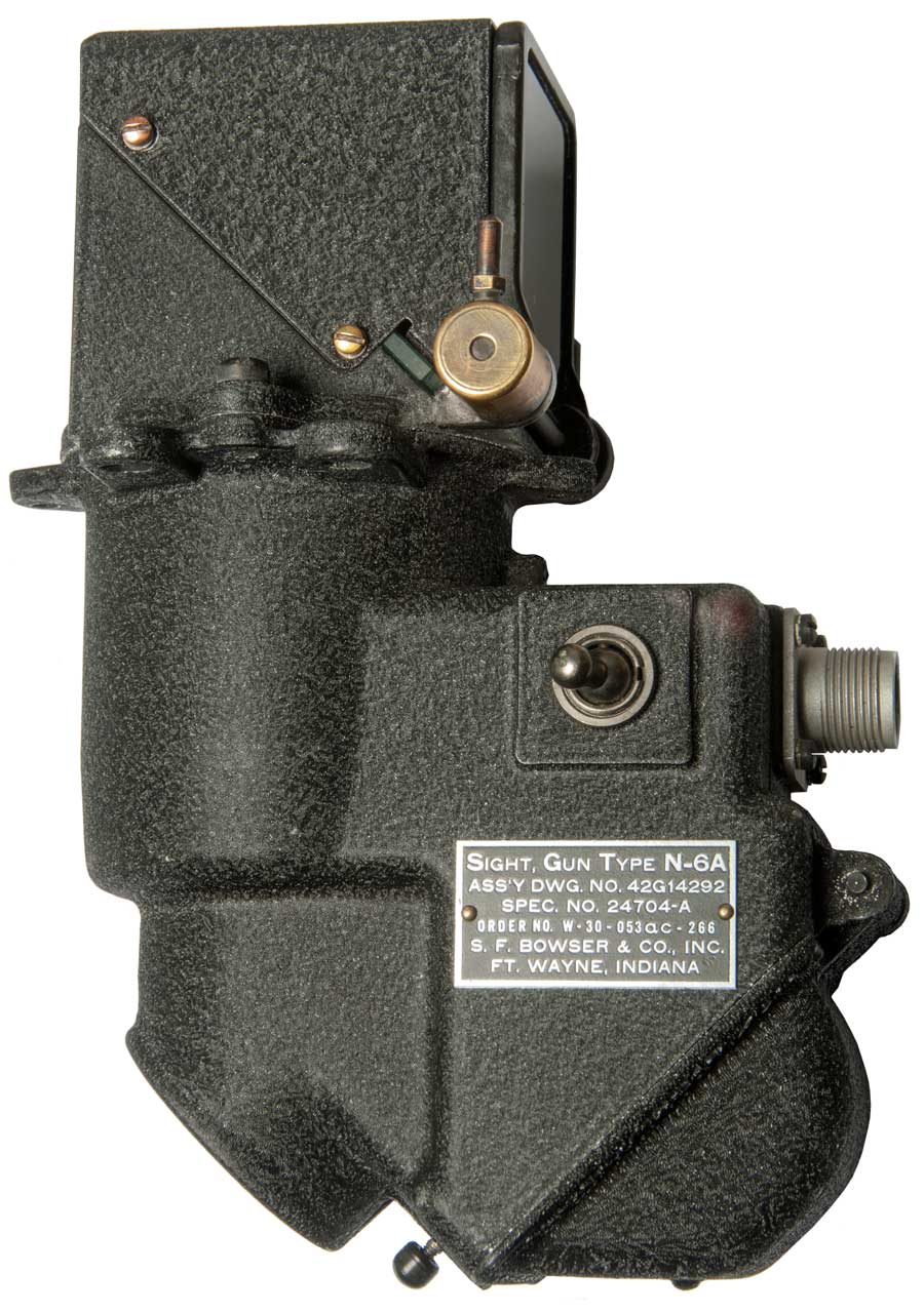
N-6A Gun Sight
This is a reflex sight, not a collimator sight. That means as your eye moves back the aiming reticle circle gets larger and at some point is so big as to not show up at all. Maybe used on "B-17G chin & tail turrets, B-24H & J nose, top, and tail turrets" according to a current eBay ad.
The "Aluminum Overcast" B-17G that visited my local airport had a N-6A (Fig 6) "Sight, Gun" marked Property of U.S. Army Air Forces, Type N-6A.
see Aircraft Gunsights - USA(A)F The N- Series. "The N-6 was the first of the N- series to be specifically designed for "flexible gunnery" for use in turrets not equipped with compensated sights."
The Army Air Force manual "Flexible Gunnery Training in the AAF" 1945, mentions K-10 & K-11 compensating sights, Computing sights, but not a definition of what it is. Flexible Gunnery" seems to be using a machine gun on a bomber to shoot down an attacking fighter. Trap shooting (Wiki) was an early training method for learning lead compensation. Flexible may refer to a type of gun mount that allows rapid motion of the gun to point at a fighter aircraft, like an aircraft turret mount (Wiki).
Also see the Aircraft Gunsights web page for US Army Air Force for the N-6.
Computing gun sights may figure out the range to the target whereas compensating gun sights, like the Navy Mk. 18 Gun Sight, contain a gyroscope.
This N-6A sight is neither computing nor compensating.
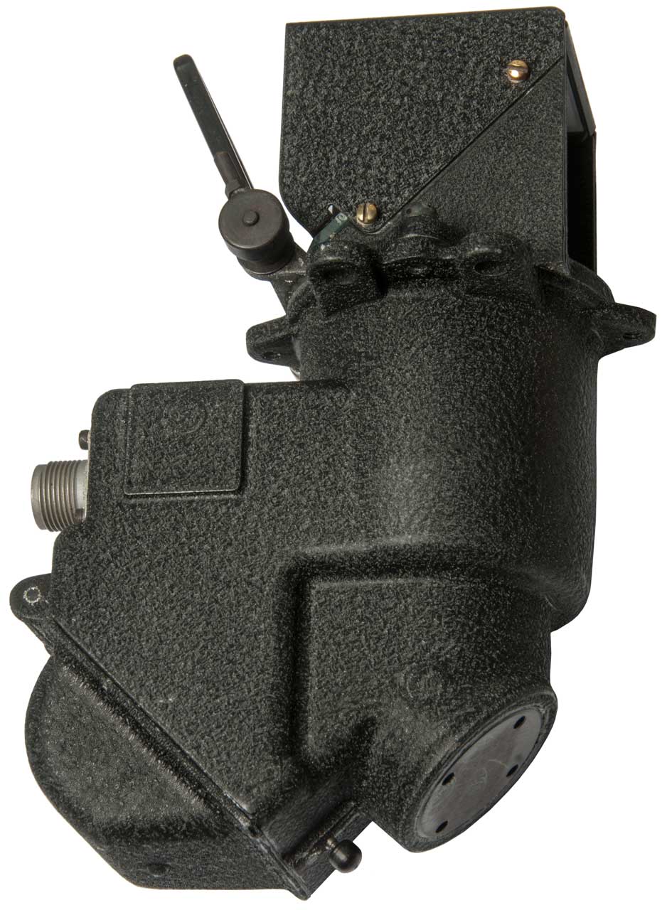
The toggle switch selects one or the other filament in the lamp. So if one filament burns out a quick flick of the switch brings the other filament into service. The On-Off function of the gun sight is controlled by a panel switch on the aircraft, maybe related to lights or guns?
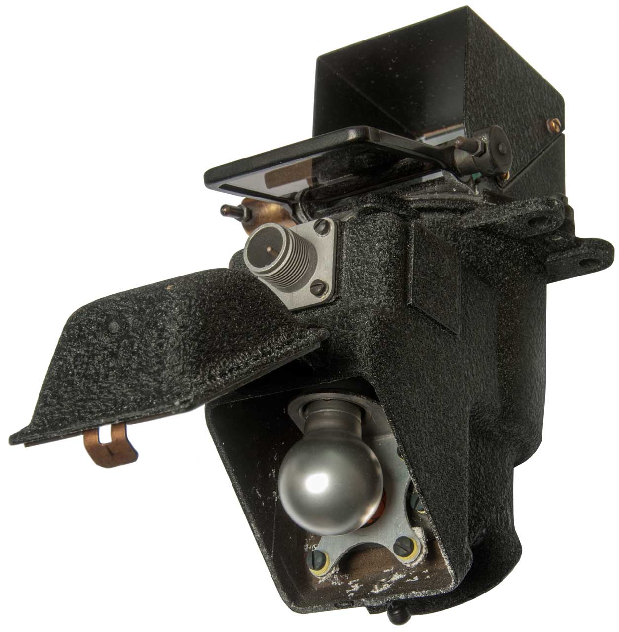
After opening the sun filter (see Fig. 2) it appeared that the 45 degree half reflecting glass was missing. It turns out that it must have very high quality anti-reflection coatings (Wiki) since it really is there.
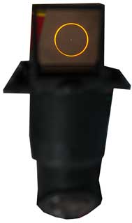
A couple of 9V batteries will light up the reticle.
Fig 1.
Fig 2.
Fig 3.
Fig 4.


Mk 20 mod 4 Description
The US Navy Gunsights were developed based on the Barr & Stroud (Wiki, patents 2190569, 2284567, 2336239, 2339578, 2360768, 236415, 2377797, 2417330) sights. The book: Naval Airborne Ordnance NAVPERS 10826-A 1958 (1961) Aircraft Reference 17 mentioned that the pilot's eye needed to be aligned with the ring and bead made its use difficult. Optical sights are easier to use. These were called "Gun Sights" even when they were exclusively used as dive bombing sights.
The Mk 20 mod 4 is a derivative of the Navy Mk 8 Illuminated Sight. These sights make use of the method of Stadia (Surveying Stadia, Wiki) to determine range to the target.
Drawing from Army, Index of Aeronautical Equipment, Volume 5 Armament, page 83.
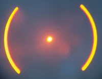
Maybe patent 2190569, 2417330 Fig 3? In any case it appears to be a very fast lens system, i.e. lens diameter is about equal to lens to reticle distance.As an example of Stadiametric Ranging suppose the wingspan of a target bomber (Wiki: Heinkel He 177) is about 31 meters. At a range of 1,000 meters (about 1,000 yards) it would subtend an angle of 31 mills, so would be about 3/5 of a 50 mil reticle circle or 3/10 of a 100 mil circle. A fighter may have a wing span of 10 meters, so the pilot would need to have some knowledge of the wingspans of different enemy planes in terms of how they appear in the reticle at a desired shooting distance. On some sights there's a knob marked in mils with various German planes marked by type, i.e. ME109, He177 &Etc).
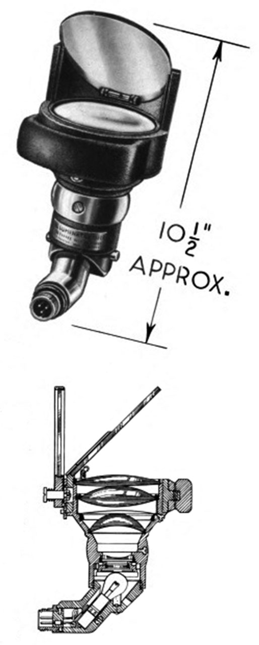
This unit consists of a Collimator where the reticle is projected on an optically coated glass plate in the head unit.
Controls and Indicators
Lamp Housing
There are a couple of sheet metal springs that when squeezed allow removal of the lamp housing.
Lamp
GE Mazda 890 21 & 21C 28V lamp. The two lugs are at the same distance from the bottom so normally could be installed two ways 180 degrees apart, but in this case it can only be installed one way because the glass bulb is not symmetrical. From the connector Ohm readings I expect a SPDT switch would be wired to select either Pin-A (filament A) or Pin-B (Filament B) with the other side of the power circuit going to Pin C. That way it would be quick and easy to switch in a new filament when one burned out.
I found it very difficult to remove the lamp requiring removing the setscrew that holds the socket into the housing and pushing the socket up. Note the pinch screw that holds the connector into the lamp housing is missing.
Note that the lamp housing can be rotated about the diameter where it mates to the sight. So it can point left, right, front, back or any angle in between.
The socket in the photo has been pulled way out from its normal position in this photo.
Connector
On Sight
Amphenol 14G-1P, 7/8-20 threads, 3 male pins marked A, B & C
Ohms table.
Pin
A
base
B
Base
C
Shell
A
-
3.2
5.9
B
-
3.1
To Make up Cable
TBD - On Order.
Head - Glass Plate
The mirror is not just glass, it has optical coatings on both faces that show up as color tints when the light is favorable.
It's 3-3/4" wide x 1/4" thick.
The angle of the mirror is adjustable by the large knob.
Head -Optics
A goal of the optical design is to make the head as small as possible with a collimated output beam as large in diameter as possible. This requires what in camera language is called a very fast lens, i.e. a lens with a very low f/number. Note that a 35mm camera lens rated at f/1.4 is considered fast.
The output lens is 3.45" diameter and the distance between that lens and the Reticle is less than 3.3" so this lens has an f/number = f/D = 3.3/3.45 = 0.95.
Note that for a Collimator (Wiki) the lens is operated with the reticle one focal length (f) from the lens and the output is a parallel light beam.
The Bar & Stroud patent 2417330 of 1947 Fig 3 shows an extremely fast lens system with f/0.73 and that has excellent color correction so the reticle image stays in focus when different colors are used. This is quite a feat of optical design.
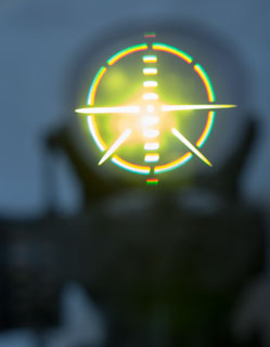
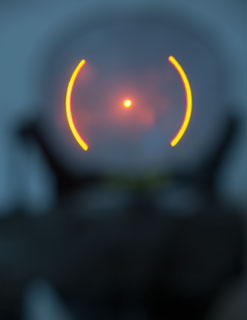
Reticles
There are 3 reticles (Wiki) just above the lamp housing. One of them is selected by the knob with two pins.
What is the purpose of these? When would each be used?
There are holes on the filter - reticle wheel that should provide detents, but they are not functional.
From http://www.aircraft-gunsights.com/reflector-sights/
This would imply the Yellow Reticle is not related to the Yellow markings on the knob.
- a Combination reticle to be used under low or medium visibility conditions that occur during dawn, twilight or heavily overcast weather conditions
- a classic “ladder type” Day reticle as night fighters and attack planes could also have to operate in day time;
- a Night reticle of reduced pattern and light intensity
Reticle Table
Color
Image
Purpose?
White
This is a 50 Mil reticle.
Yellow
Just above photo
"100 Mils"
Daytime Guns
See Aircraft-Guns Mk20 Mod 4
On this "Ladder100 Mil reticle the steps are 20 Mils apart.
Orange
looks like rocket reticle on L-9 gunsight
This is a 50 Mil reticle.
Knob
Turning the knob tilts the reflector plate. The knob is marked Mils (Wiki: Milliradian). There are 2000 * PI (6283.185 ) mils in a circle.
At a distance of 1,000 a one mil change is 1. The units can be anything but they must be the same units, typically yards.
The book: Naval Airborne Ordnance NAVPERS 10826-A 1958 (1961) Aircraft Reference 17, page 217 says "During a single mission, the line of sight may be changed rapidly and accurately to the offset required for fixed gun firing and the releasing of rockets, bombs, or any combination of the three types and sizes of armament." The actual method of presetting the detent is covered in detail in OP 1671.
There are markings both on the knob and around the index. The index is marked 40 - 0 - 40 MILS.
Note that 20 mils separation on the index scale corresponds to 20 separation on the knob markings, so the knob is also in mils
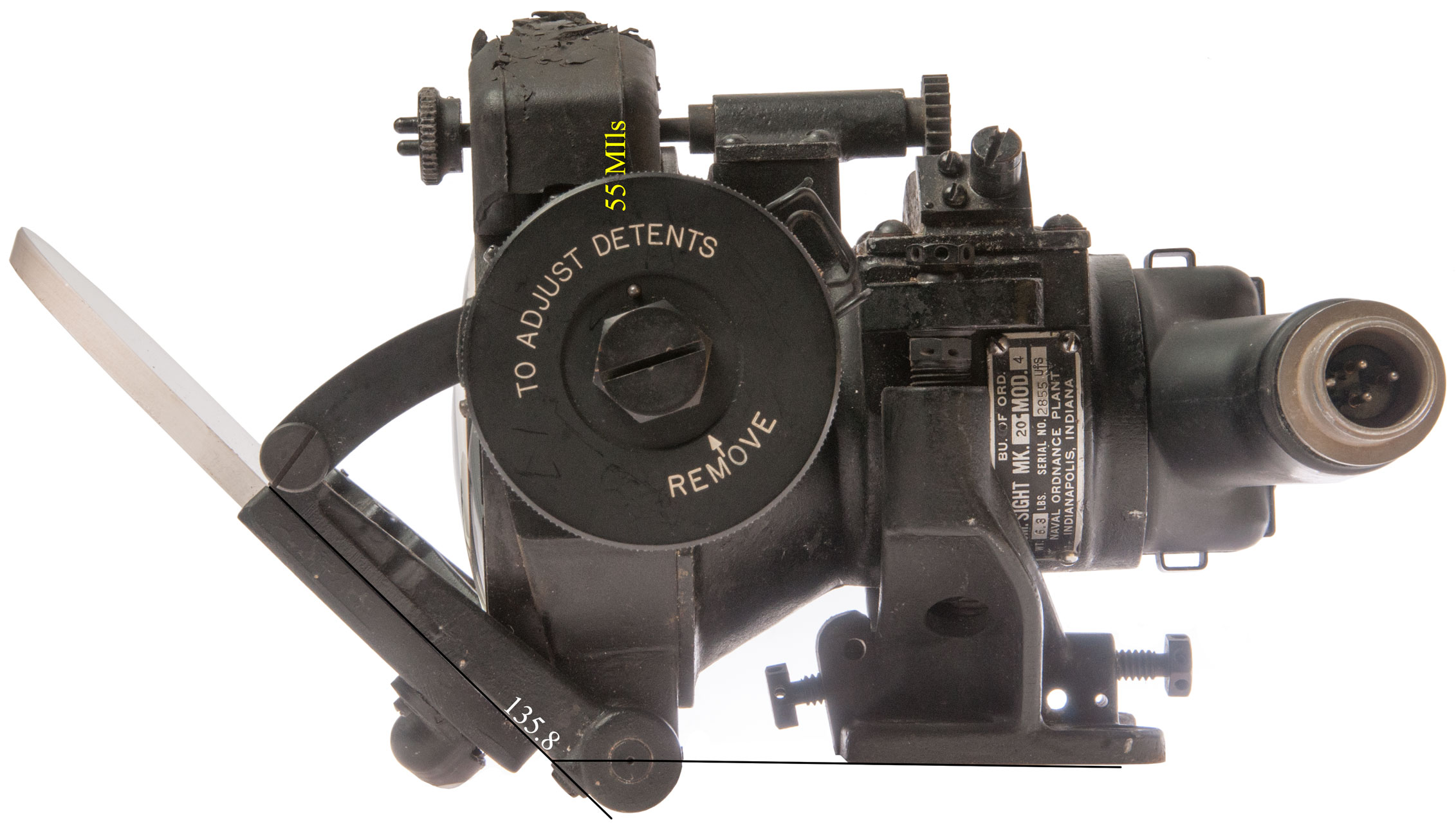
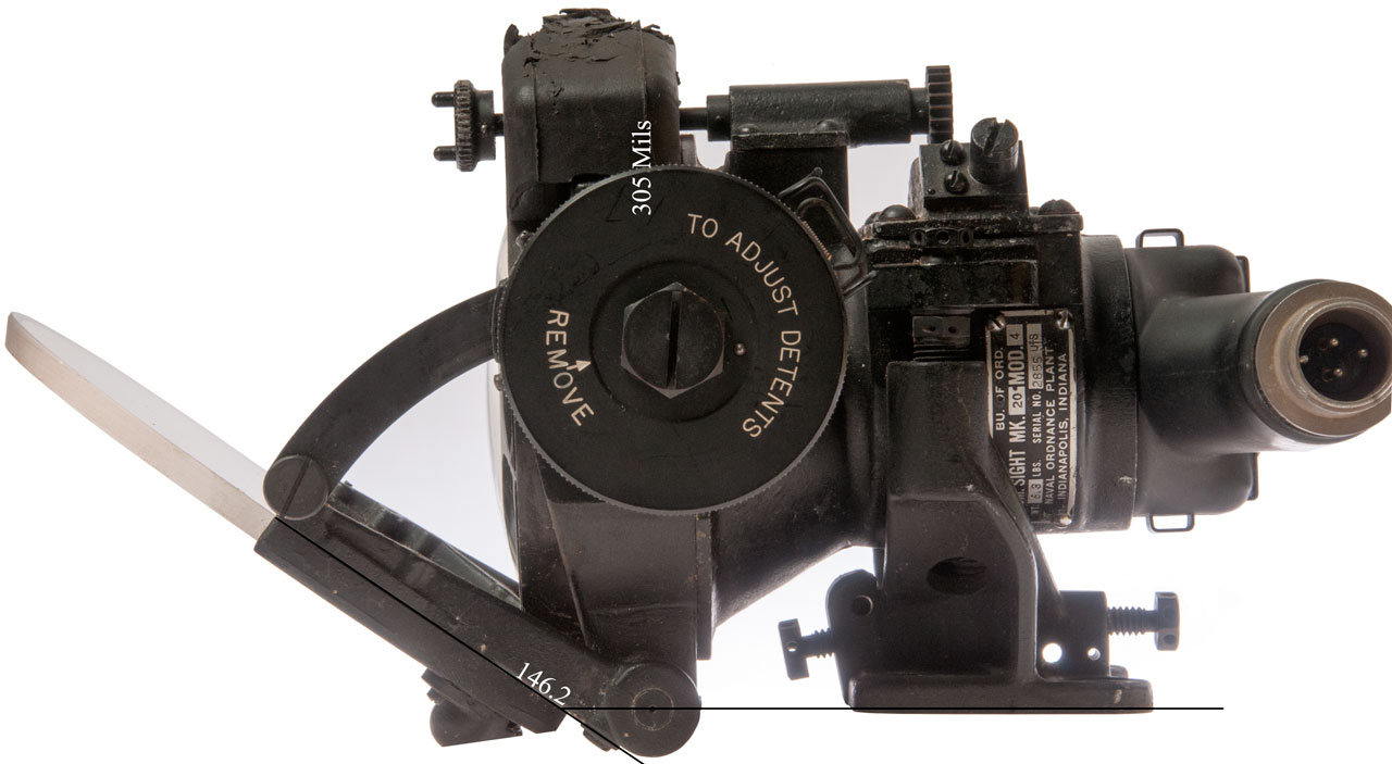
The knob is marked in Yellow from 75 to 0 and in white from 0 to 350. But the actual knob movement is from 55 Yellow to 305 White which are the two settings in the below photos.
It may be that the yellow knob markings are related to the yellow reticle above and in a like manner the white reticle relates to the white markings.
The difference between the extreme readings is 146.2 - 135.8 = 10.4 deg or 181 mills.
The difference in knob readings is 305 + 55 = 360 mills. But because of the reflection the relationship between plate degrees and mils is:
2 * Mils = Plate movement in degrees.
The above readings are based on the white mark on the lamp support wire ring, not the zero index mark. So the 305 limit is really280 White and the 55 Yellow is really past 70 Yellow. But the delta readings stay the same.
Note index markings of 40 to 0 to 40.
Also note the white index on the lamp support ring that's not at the 0 index mark.
A source of confusion!
The rubber crash pad has seen better days.
Knob at 55 Yellow
where 135 degrees would be a 45 degree angle of the plate, so the zero index mark is not at 45 degrees.
135.8 degrees.
PS the (-) screw at the top right holds a spring that maybe should press a ball to form a detent for the reticle selection wheel.
Knob at 305 White.
146.2 degrees.
A Quarter is too big, so I used a wrench to remove cap to expose Detent adjustments.
It appears that there a 4 detents possible.
They are set to:
40 Yellow
0
40 White
? not set or 285 Knob will not turn past 285, but should turn to 350, why?
There is a tall pin just above the letter "E" in SCREWS" and it must mate with the hole in the cap.
Mk 20 Documents
OP 0 - Index of Ordnance Publications 7 May 1946 (447 pages)
NARA Record Group 74: Records of the Bureau of Ordnance, 1818 - 1967: Ordnance Pamphlets Finding Aid -
ID
OP No.
Vol
Part
Title
Last
Date
Subject
Type
Withdrawn
Box
No.
267
0263
Aircraft machine gun sights (TM 1-495) 3/1/1941 Aviation Ordnance No
39
555
0531
Aerial Sights and Sighting 8/1/1919 Aviation Ordnance No
79
735
0803
Illuminated sight, Mark 8 10/20/1950 Aviation Ordnance No 137
0803A
Illuminated Sight Mk 8 and Mods Parts Catalog
Nov 1941
775
0611
Aviation Ordnance, Bomb Sight Mk. 15 7/1/1937 Aviation Ordnance No
95
781
0638
Aeronautical Bomb Sight Mk. 15 Mod. 3--Parts Catalogue 7/1/1940 Aviation Ordnance No
103
783
0640
Aviation Ordnance Bomb Sight Mk. 15 Mod. 4 and 5--Parts Catalogue 1/1/1941 Aviation Ordnance No
103 - 104
787
0649
Aviation Ordnance, Bomb Sight Mk. 15 Mods. 4 and 5--Operation 6/1/1943 Aviation Ordnance No
107
788
0605
Aviation Ordnance, Bomb Sight Mk. 15 Mods. 4 and 5--Maintenance 10/1/1941 Aviation Ordnance No
107 - 108
817
0863
Aircraft Gun Sight (Illuminated), Mk. 9 8/30/1945 Aviation Ordnance No
152
938 0803A
Illustrated Parts Catalogue for Illuminated Sight Mk. 8 7/1/1944 Aviation Ordnance No
137
940
0863A
Illuminated Sight Mk. 9 and Mk. 9 Mod. 1--Parts List 10/1/1943 Aviation Ordnance No
152
1069
1043
Service Manual for Gun Sight Mk. 18 and Mods. And Voltage Regulator Mark 1 9/1/1943 Aviation Ordnance No
188
1082
0601
Bomb Sight, Mark XI, Description and Operation 8/1/1928 Aviation Ordnance No
94
1212
1098
Gun Sight Mark 15, Mods 2 and 3 4/7/1950 Aviation Ordnance No
203
1318
1216
Gun Sight Mark 23 Mod. 0 4/8/1945 Aviation Ordnance No
234
1420
1325
Gunsight Mark 20 Mods. 3 and 5 4/4/1947 Aviation Ordnance No
251
1421
1325A
Gun Sight Mark 20 Mods. 3 and 5 10/16/1947 Aviation Ordnance No
251
1431
1337
Sighting Data for Fixed-Gun Strafing, Rocket Firing, and Bombing Aircraft TBM-1C and TBM-3 Fixed Gunsight 4/25/1946 Bombing Table No
255
1444
1354
Sighting Data for Fixed-Gun Strafing, Rocket Firing, and Bombing Aircraft F4U-1, F4U-1D, F4U-4, F4U-5, FG-1, F3A Fixed Gunsight 3/28/1946 Bombing Table No
258
1445
1355
Sighting Data for Fixed-Gun Strafing, Rocket Firing, and Bombing Aircraft F6F-3 and F6F-5 Fixed Gunsight 12/27/1945 Bombing Table No
258
1447
1357
Sighting Data for Fixed-Gun Strafing, Rocket Firing, and Bombing Aircraft TBM-1C and TBM-3 Fixed Gunsight 4/25/1946 Bombing Table No
259
1448
1358
Sighting Data for Fixed-Gun Strafing, Rocket Firing, and Bombing Aircraft SB2C-1, SB2C-1C, SB2C-3, SB2C-4 and SB2C-5 Fixed Gunsight 6/11/1946 Bombing Table No
259
1488
1421
Sighting Data for Fixed-Gun Strafing Caliber .50 and 20-mm Fixed Machine Guns 4/28/1945 Bombing Table No
264
1523
1466
Sight Settings for Masthead Bombing at Altitudes 50-500 feet 8/14/1945 Bombing Table No
271
1532
1478
Rocket Sight (Aircraft) Mark 1 Mod. 0 7/10/1945 Aviation Ordnance No
272
1533
1480
VT Fuzes for Projectiles and Spin-Stabilized Rockets 6/1/1962 Ammunition No
272
1534
1480A
VT Fuzes for Spin Stabilized Rockets Characteristics and Operational Use 7/23/1945 Ammunition No
272
1543
1494
Mounting Bracket (Illuminated Sight) Mark 1 Mod. 3 Service Manual 4/25/1945 Aviation Ordnance No
274
1610
1597
Sighting Data for Fixed Gun Strafing, Rocket Firing, Bombing, Aircraft F7F-2N Fixed Gunsight 4/11/1947 Bombing Table No
290
1611
1598
Sighting Data for Fixed Gun Strafing, Rocket Firing, Bombing, Aircraft F8F-1 Fixed Gunsight 7/11/1946 Bombing Table No
290
1312
1599
Sighting Data for Fixed Gun Strafing, Rocket Firing, Bombing, Aircraft PV-2 Fixed Gunsight 4/11/1947 Bombing Table No
290
1690
1670
1
Aircraft Sight System Mark 1 Mods. 0, 1, and 2 Operation, Description, Installation, Installation, and Line Maintenance 8/8/1947 Aviation Ordnance No
318
1691
1670
2
Aircraft Sight System Mark 1 Mods. 0-3 Overhaul and Parts Catalog 9/27/1951 Aviation Ordnance No
318
1692
1671 1 Illuminated Sight Mark 20 Mod. 0 Description, Operation, Installation, and Maintenance 4/16/1947 Aviation Ordnance No 318 1693
1671
2
Illuminated Sight Mark 20 Mod. 0 Overhaul Parts Catalog 6/7/1949 Aviation Ordnance No
318
1719
1709
1
Gun Sight Mark 18 Mod. 6 Description, Operation, Installation, Maintenance, Theory, Preservation, Packaging, and Storage 11/14/1951 Aviation Ordnance No
326
1720
1709
2
Gun Sight Mark 18 Mod. 6 Overhaul Parts Catalog 11/14/1951 Aviation Ordnance No
326
1781
1800
Sighting Data for Fixed-Gun Strafing, Rocket Firing, Bombing Aircraft AD-1 Fixed Gunsight 2/15/1949 Bombing Table No
359
1784
1802
Sighting Data for Fixed-Gun Strafing, Rocket Firing, Bombing Aircraft F4U-4B and F4U-5 Fixed Gunsight 4/26/1949 Bombing Table No
359
1832
1833
1
Sight Unit Mark 6 Mod. 1 and Amplifier Mark 53 Mod. 0 Installation, Operation, and Maintenance 3/7/1952 Aviation Ordnance No
374
1833
1833
2
Sight Unit Mark 6 Mod. 1 and Amplifier Mark 53 Mod. 0 Overhaul Instructions and Illustrated Parts Catalog 3/7/1952 Aviation Ordnance No
374
1855
1870
Gun Sight Mark 20 Mods. 6-7 Description, Operation, Theory, Installation, and Shipboard Maintenance 7/11/1953 Aviation Ordnance No
394
1856
1870A
Gun Sight Mark 20 Mods. 6-7 Maintenance Manual 12/24/1952 Aviation Ordnance No
394
1898
1940B
Gunsight Mark 31 Mods. 1-5 and Amplifier Mark 121 Mods. 1-3 Overhaul 11/1/1961 Aviation Ordnance No
412


Photos
Fig 1 Double Boxed (Excellent Packaging)
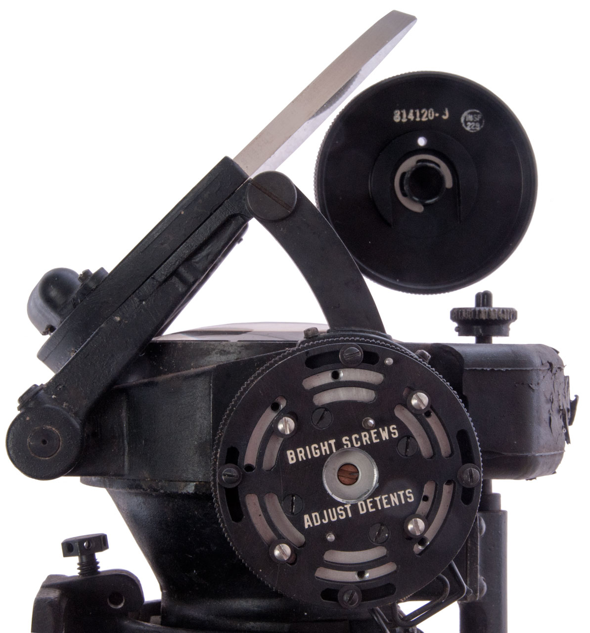
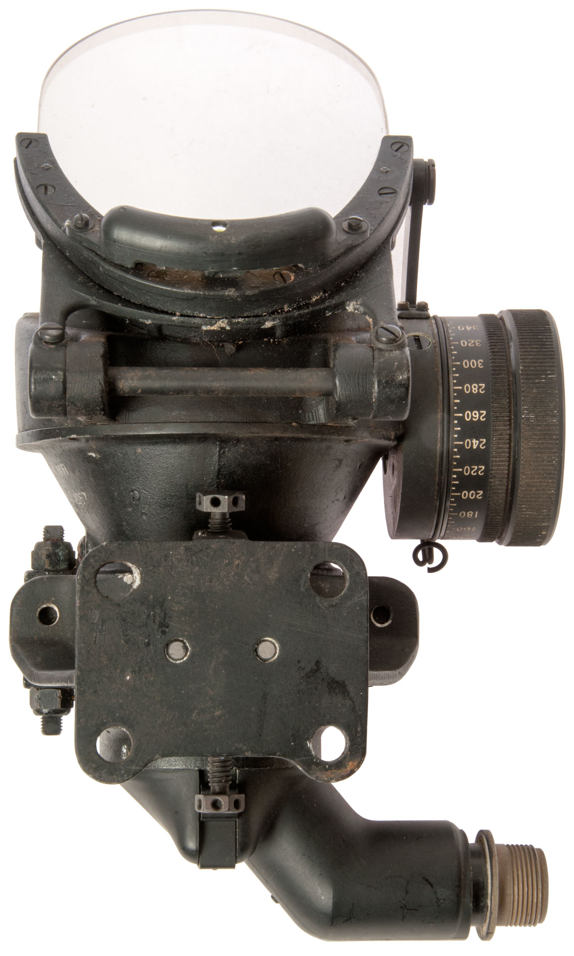
Fig 3 Top View

Fig 11 Bottom View
Reticle Wheel (Lamp housing removed)
Flashlight aimed at lens from top.
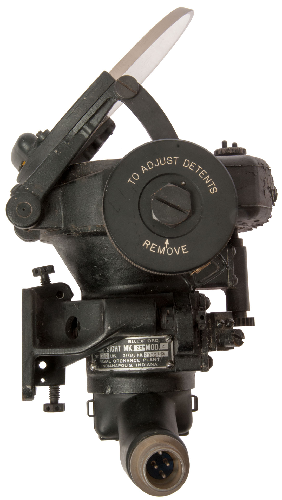
Fig 4 Left View
The dial drives the arm just above it to change the tilt angle
of the glass plate.
Bolts at left near mounting bracket adjust for and aft tilt,
i.e. for setting the knob zero.
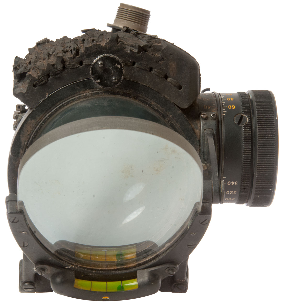
Fig 2 Pilot's View
The wire spring clip just below the Dial on the left is to hole
a small light. The numbers on the dial do not glow under UV.
On the right are two nuts that allow adjusting the left-right
tilt of the sight relative to the mounting bracket.

Fig 5 Right View
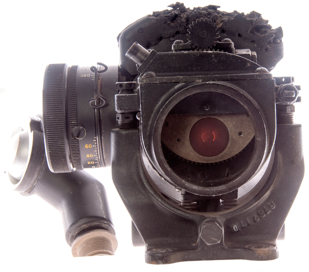
Fig 6 Front View
Mounting bracket with 4 holes.
Castle nuts above and below it for front-back tilt adj.
Nuts at left for left-right tilt adj.
Use?
Fig 7 Bottom View (with Lamp Housing)


Patents
1031769 Optical instrument, Archibald Barr, William Stroud, 1912-07-09 - Barr & Stroud (Wiki) - stabilized ship's telescope
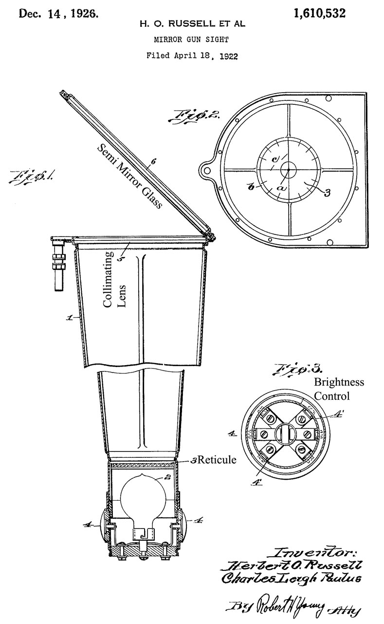
1610532 Mirror Gun Sight, Russell Herbert Owen, Paulus Charles Leigh, 1926-12-14 - to replace ring and bead sights
1724093 Automatic compensating gun sight, Robert Kauch & Charles L. Paulus, 1929-08-13 - used with a Lewis Gun (Wiki) on bi-planes (Wiki).
1821431 Diving bomb sight,Gardner Grandison, 1931-09-01 -"...The steeper the dive, the more accurate"..."a fixed rear sight and a movable front sight adjustable in proportion to the altitude and airspeed..." pilot enters starting altitude and sight contains wind speed mechanism.
2160202 Range-finding and fire-correction, Jean Fieux, Schneider & Cie, 1939-05-30, - a collimator reflex sight with a circle whose diameter can be changed to match the size of a plane.
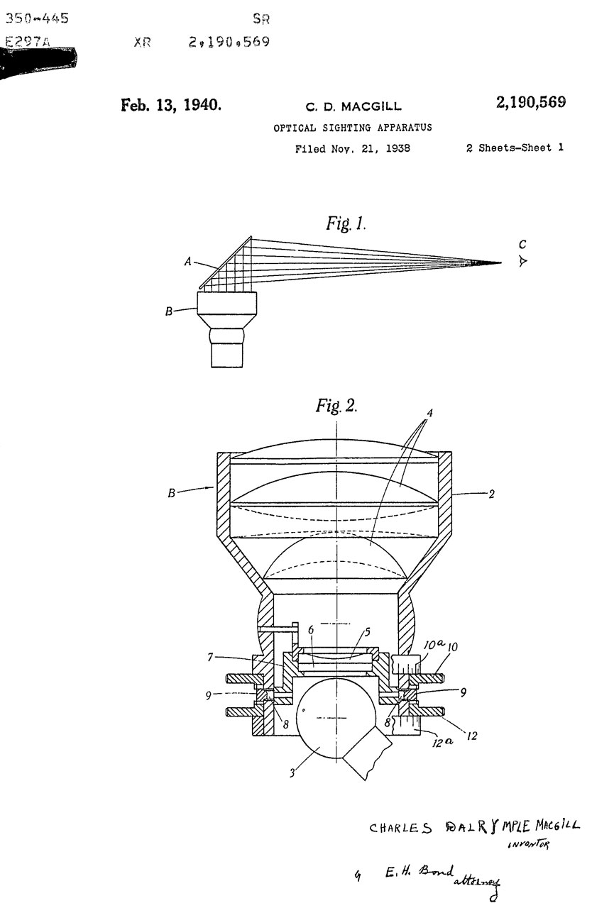
2190569 Optical sighting apparatus, Macgill Charles Dakymple, Barr and Stroud Ltd, 1940-02-13 - Reflector Gun Sight Mk II, Spitfire
GB No. 504845/1937
2284567 Lens for optical purposes, French James Weir, Barr and Stroud Ltd, 1942-05-26 - for Collimator gun sights
" a single double-convex lens of the type having one surface of paraboloidal form and the other of spherical form in which the ratio of focal length to aperture can be reduced to a degree such as, it is believed, has only been obtained by means of complex lens combinations."
2291612 Turn Indicator, Charles S Draper, Sperry Gyroscope Co, 1942-08-04 - used on K14 gunsight
RE22330 Turn Indicator, C.S. Draper, Sperry Gyroscope Co, June 8, 1943 - "... the amount of precession from the neutral position is approximately proportional to the rate of turn..."
2307590 Means for indicating turning movements of a craft, Theodore W Kenyon, SPERRY GYROSCOPE CO Inc, 1943-01-05 - intended for blind flying on board aircraft, but also used for the K14 gunsight used on navy ships for anti-aircraft fire.
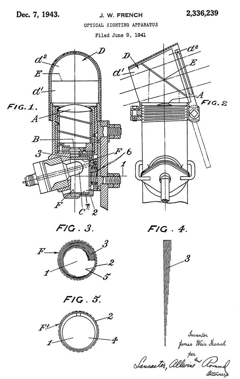
2336239 Optical sighting apparatus, French James Weir, Barr and Stroud Ltd, 1943-12-07 -
to change brightness of reticle a variable density optical system( Fig 3, 4 & 5) is used instead of a rheostat in the lamp circuit.
drawings same as 2336239 above.
2339578 Optical sighting apparatus, Macgill Charles Dalrymple, Barr and Stroud Ltd, 1944-01-18 -
The hood is shaped to match the light cone going to the pilot's eye maximizing field of view.
Later sights eliminated the hood.
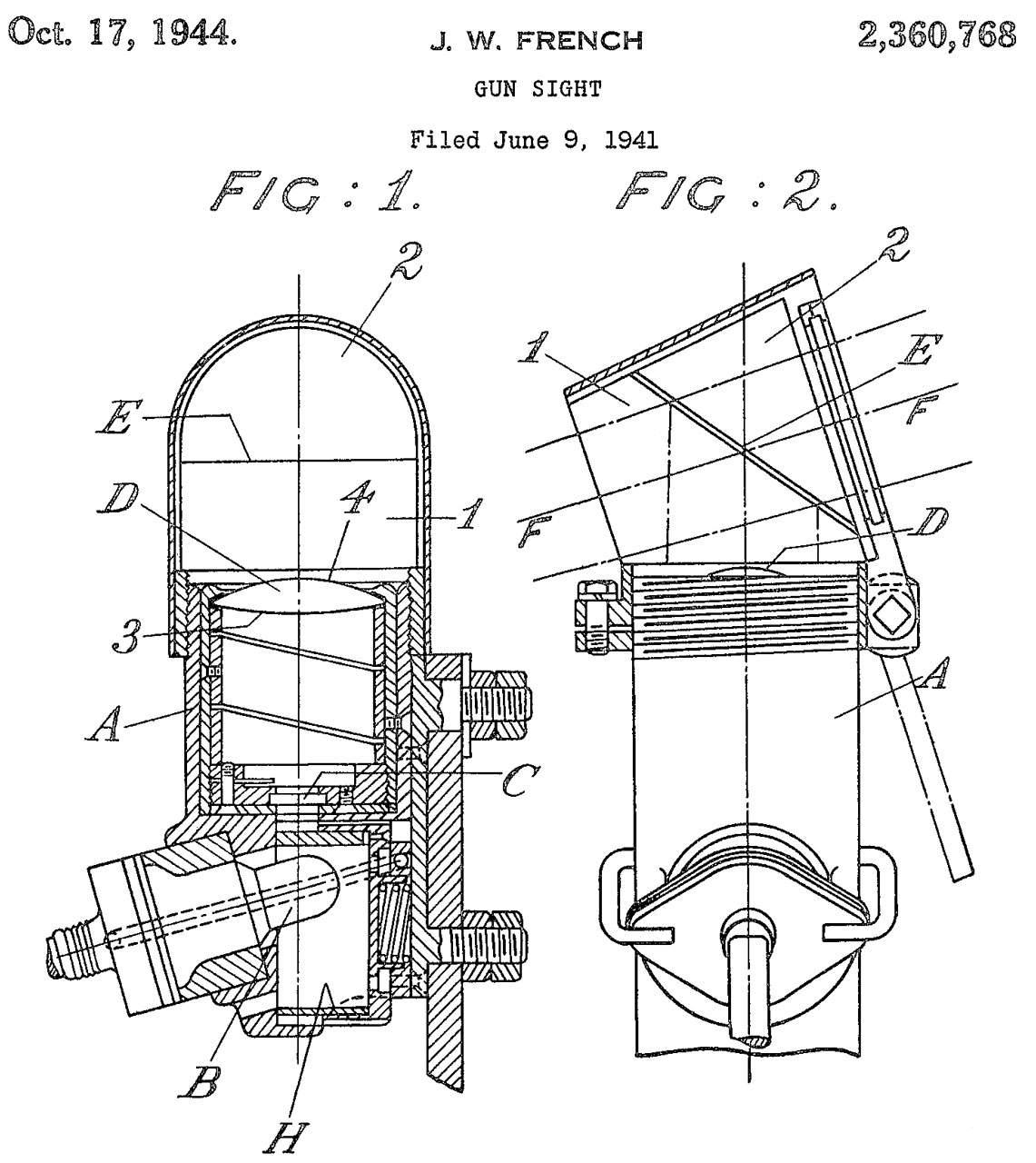
2360768 Gun sight, French James Weir, Barr and Stroud Ltd, 1944-10-17 -
This patent covers the collimating optics, but appears to be the same as patent 2336239 above.
2364152 Sight for guns, Macgill Charles Dalrymple, Barr and Stroud Ltd, 1944-12-05 -
spherical bearing on optical axis to align - an expensive way - probably never used.
2367207 Combination bomb and gun sight head, Earl E Flint, 1945-01-16 - Collimator sight
" adjusting means for combined gun and low altitude bomb ing sights, and has for an object the provision of adjustable sighting means for a collimator Sight that is simple and positive in operation, including releasable locking means for positively maintaining the sight in a gun sighting position, together with positive stop means for quickly adjusting the sight to a plurality of predetermined low altitude bombsighting positions."
Note this is a head for use on the common Collimator sight, like the NC-3
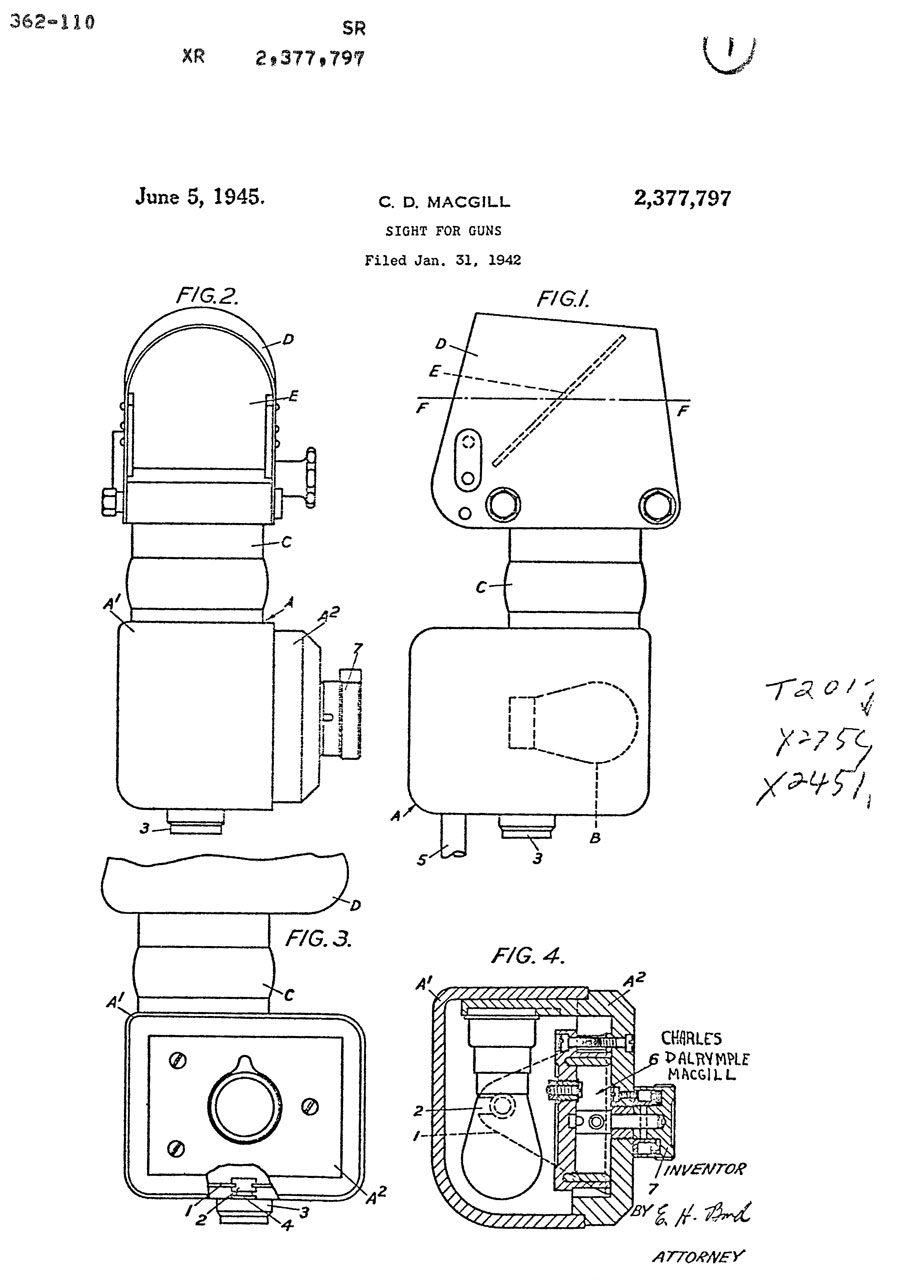
2377797 Sight for Guns, Macgill Charles Dalrymple, Barr and Stroud Ltd (Wiki, History) 1945-06-05 - removable lamp housing for easy lamp change
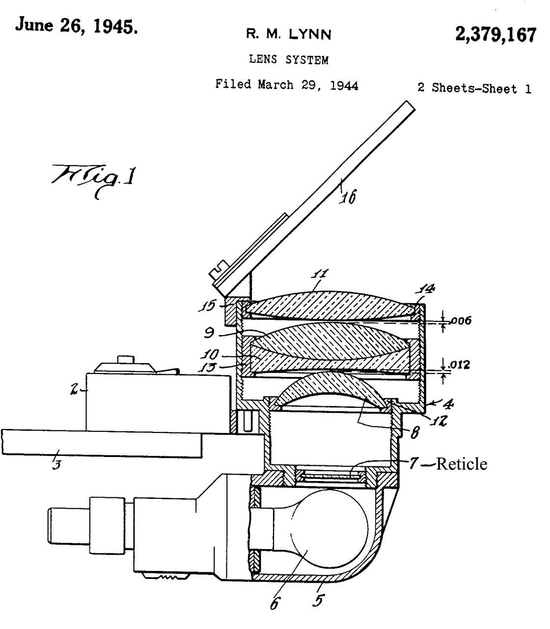
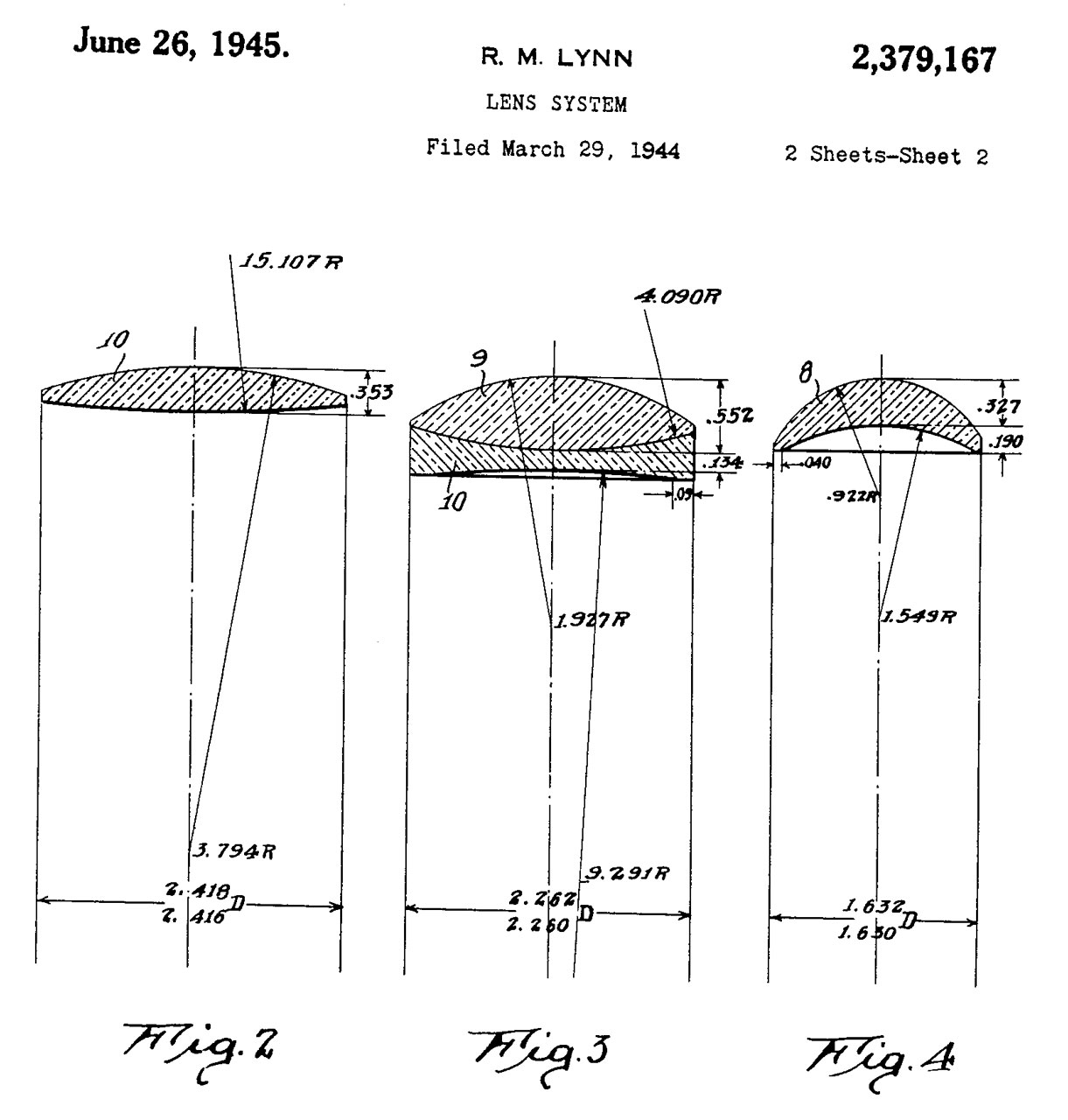
2379167 Lens System, Robert M Lynn, 1945-06-26 - 2-3/3" dia & f/0.069
The system is composed of three lens groups (Fig 4, Fig 3 & Fig 2).
L-9 Gunsight see: Aircraft-Gunsights
"
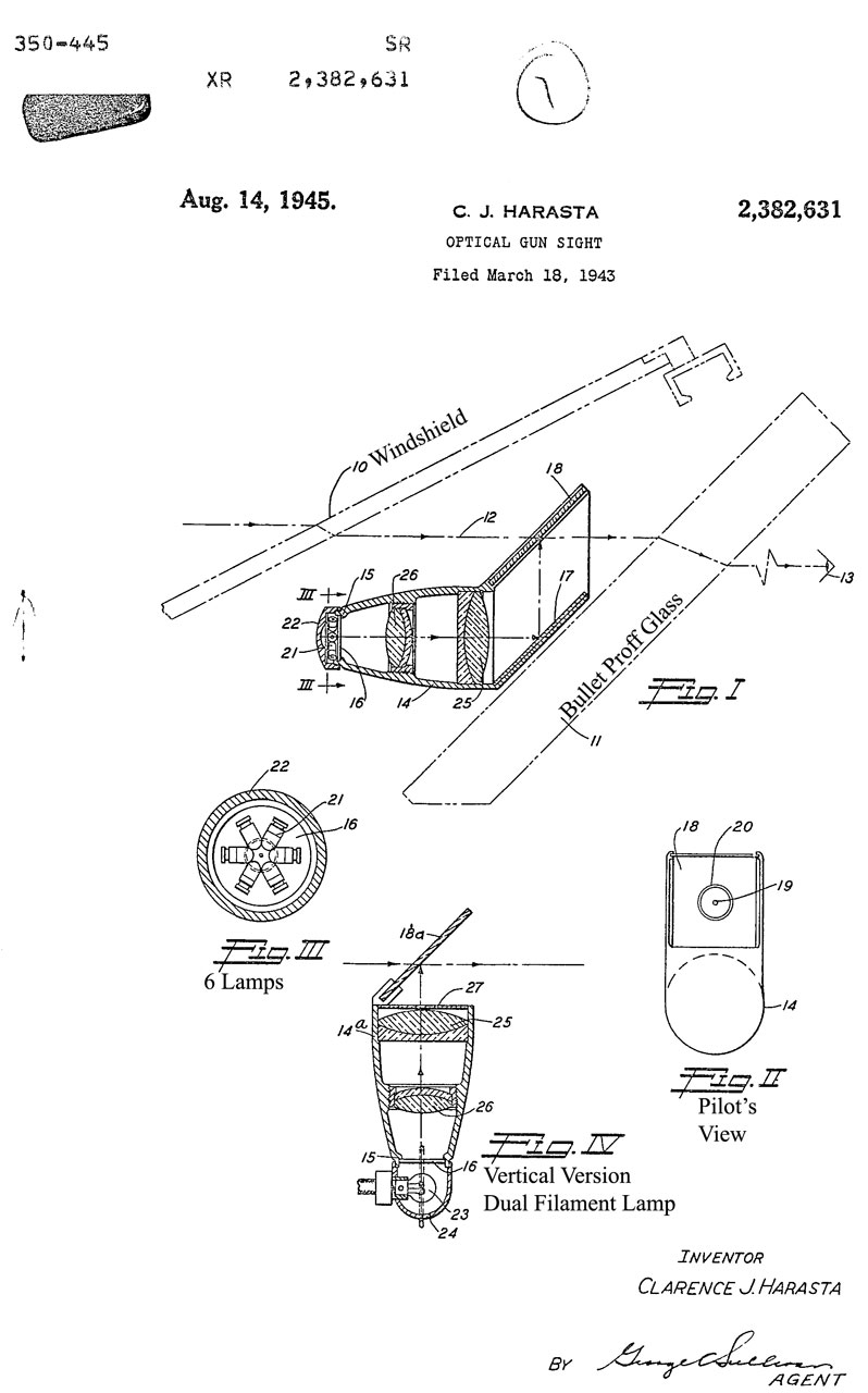
2382631 Optical gun sight, Clarence J Harasta, Lockheed Corp, 1945-08-14 - "As an example of current practice, government furnished sights for the P-38 have a focal length of approximately 7-1/2 inches with a working diameter of 2-1/4 inches and therefore must be so mounted that the semi-reflector surface is disposed at an angle of approximately 20 to the optical axis, requiring a very long and expensive reflector. By radically changing the design of the sight I have been able to produce an improved sight having the same working area or field of view in a focal length of 2 inches or less, and weighing but a fraction of that of the present design. Calls
1610532 Mirror Gun Sight, Russell Herbert Owen, Paulus Charles Leigh, 1926-12-14 (see above)
2384036 Torpedo Director, Wolfgang B Klemperer, Sydney J Goldberg, Douglas Aircraft Co Inc, 1945-09-04 - solves triangle: moving plane, moving ship, time from launch to hit -forward facing like gun or dive bombing sight.
2384643 Objective for reflex sight, Schade Willy, Eastman Kodak Co, 1945-09-11 -
"An object of the invention is to provide a lens which is corrected for chromatic aberrations and coma and extremely well corrected for spherical aberration including zonal spherical aberration and which is very suitable for use at high apertures; i. e., about f/2.4 to about f/1.2 or even higher."
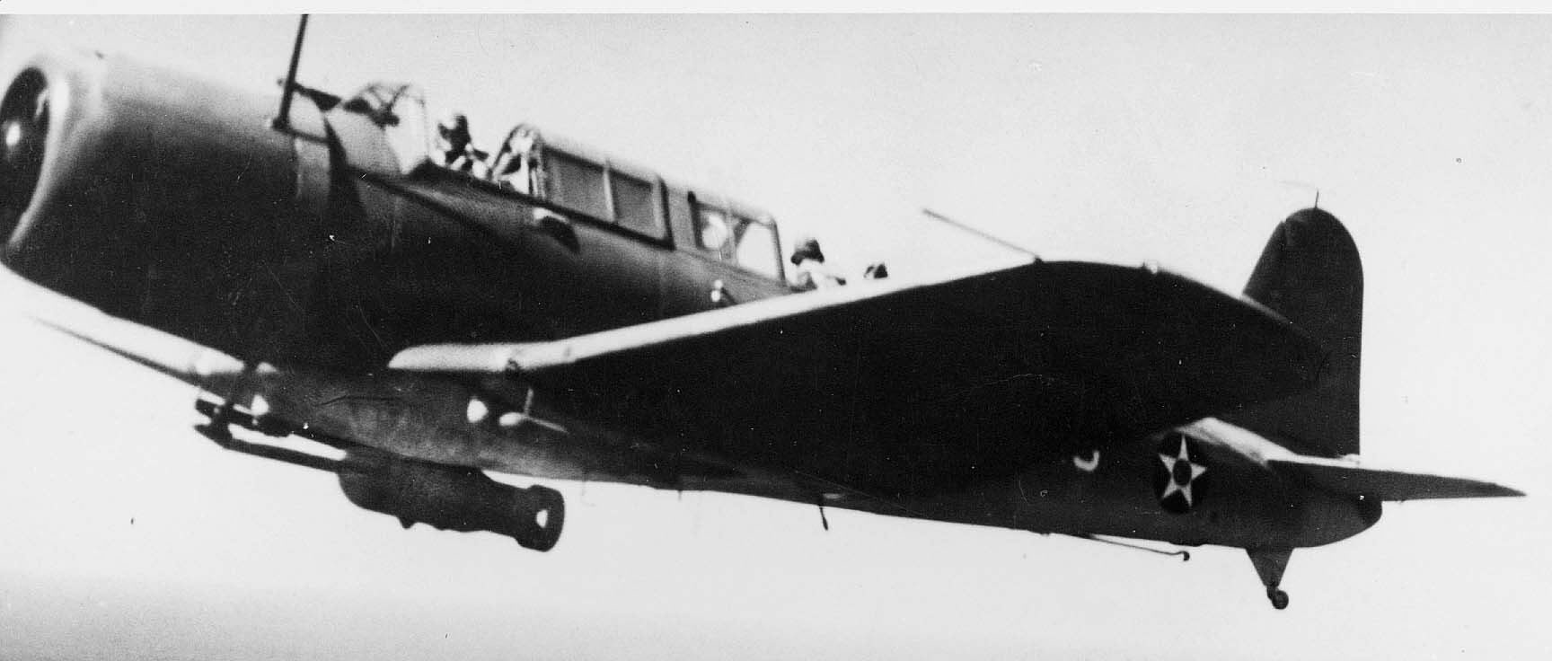
2397711 Vought SB2U Vindicator Photo from Wiki: SB2U
2397711 Gun Sight, Russell R Vought, Filed: Jan 17, 1941, Pub: 1946-04-02 - combines dive bombing sight with indicator to show a 70 degree dive angle (a 0 deg dive angle would be horizontal, 90 deg is straight down, and over 90 deg is upside down).
looks like the dive bombing sight on the Vought SB2U Vindicator dive bomber
In photo at left notice:
1. Sight in line with pilot's heat facing forward,
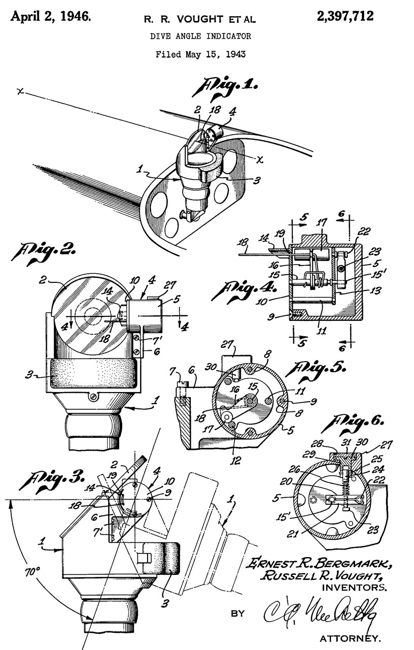
2. Swing-out bomb rack to move bomb outside propeller disk.2397712 Dive angle indicator, Russell R Vought, Filed: May 15, 1943, Pub: 1946-04-02
Because of the 1943 filing date this is probably the Mk 8 sight.
Vought Aircraft (Wiki) - F4U Corsair (Wiki) 1940 to 1979 - Used the Mk 20 Mod 4 sight
2405263 Bomb Sight, Robert M Lynn, 1946-08-06 - collimating reflex sight, bombs or guns, - azimuth and elevation movement of glass plate.
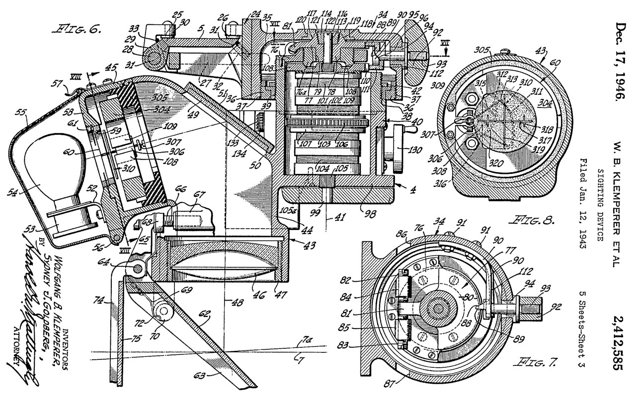
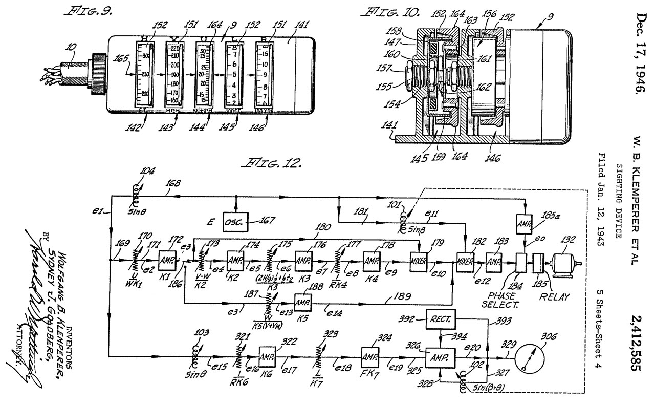
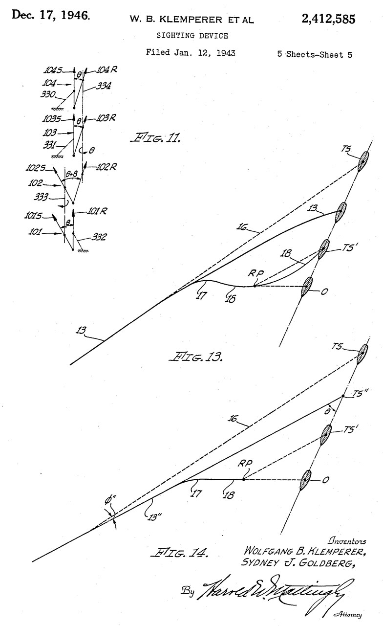
2412585 Sighting Device, Wolfgang B Klemperer, Sydney J Goldberg, Douglas Aircraft Co Inc, 1946-12-17 -for: Torpedoes, guns or bombs - analog electronic computer - requires 5 inputs (seems like to much to guess at).
related:
2439365 analog electrical computer for vectors,
2427463 Apparatus for making computations electronically
2417330 Lens for optical purposes, Strang John Martin, Barr and Stroud Ltd, 1947-03-11 -
Compound lens with more corrections than simpler lens.
"..a lens in which the relative aperture, i. e. the ratio of aperture to focal length, Will be comparatively large and the lens well corrected for spherical aberration when used in monochromatic or approximately monochromatic light"
Fig 1 is a simple version (f/2.7)
Fig 2 has a compound rear element (f/1.19)
Fig 3 allows for focusing (f/0.73)
2425400 High aperture collimating lens system, Schade Willy, Eastman Kodak Co, App: 1943-11-27, W.W.II, Pub: 1947-08-12, - 6 complex lenses to form collimator
2426744 Automatic gun compensator, George W Pontius, Arthur P Wilson, Bendix Aviation Corp, App: 1942-01-23, W.W.II, Pub: 1947-09-02, - takes into account Angle of Attack - works with 4 machine guns.
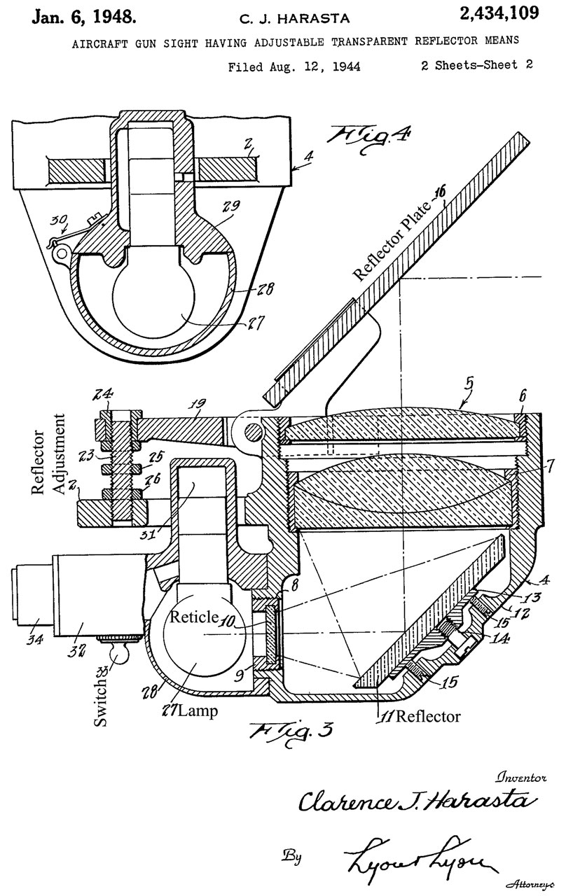
2434109 Aircraft gun sight having adjustable transparent reflector means, Clarence J Harasta, 1948-01-06 - earlier version of NC-3?
calls:
2367207 Combination bomb and gun sight head, Earl E Flint, 1945-01-16
2379167 Lens System, Robert M Lynn, 1945-06-26 - 2-3/3" dia & f/0.069
2377797 Sight for Guns, Macgill Charles Dalrymple, Barr and Stroud Ltd, 1945-06-05 - easy lamp change2354720 Low altitude bomb sight, Walter J Wagner, 1944-08-01 - add on to NC-3?
2284150 Film inspecting apparatus
2453122 Reflector collimator sight for torpedo ejectors, Willis B Ensinger, Navy, App: 1944-07-06, W.W.II, Pub: 1948-11-09, -
2461967 Aerodynamic Retarder, Leo J Devlin, Edward H Heinemann, Douglas Aircraft Co Inc, 1949-02-15 - "...actuated preparatory to initiating or terminating a. dive..."
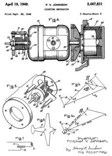
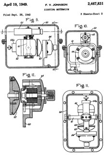
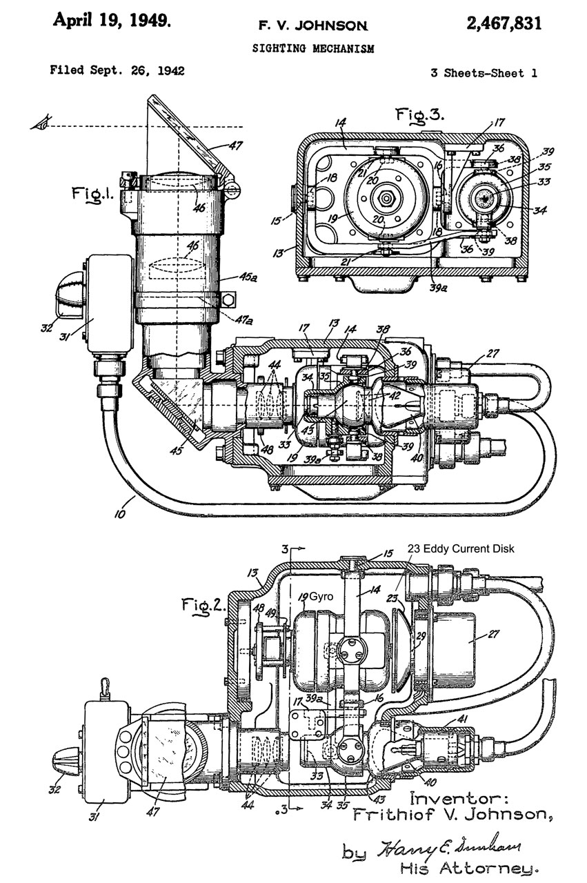
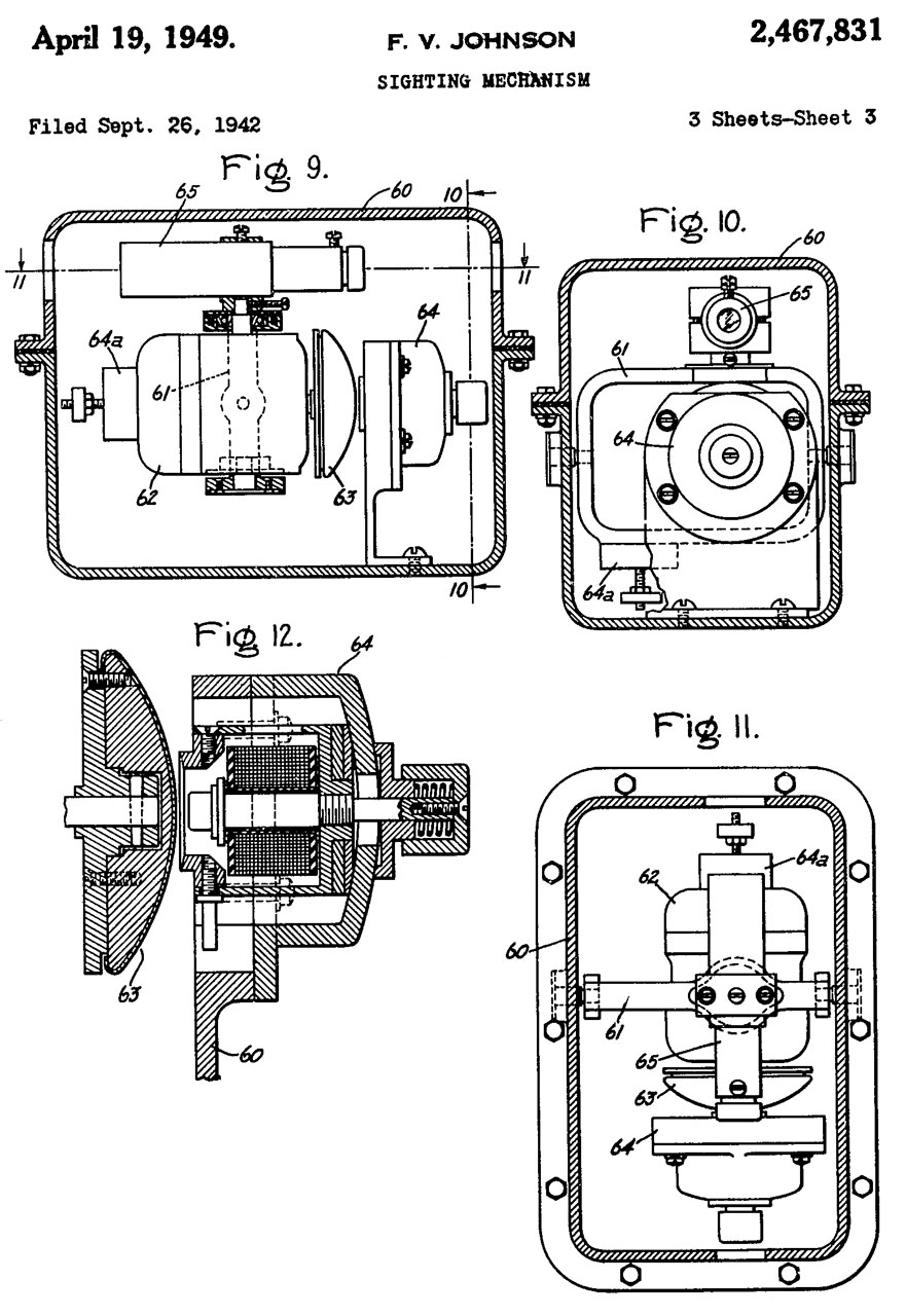
2467831 Sighting mechanism, GE, 1949-04-19 - for use on aircraft mounted machine guns
2482699 Gunfire control apparatus, Hary F. Vickers, Vickers Inc, App: 1943-03-02, Pub: 1949-09-20, -
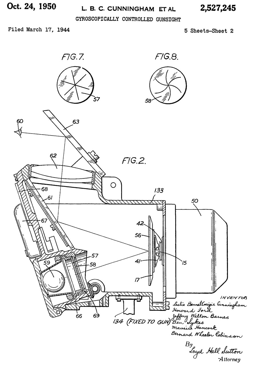
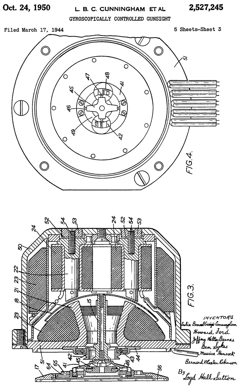
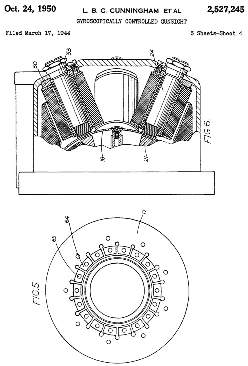
2527245 Gyroscopically controlled gunsight, Ford Howard, Barnes Jeffery Walton, Sykes Ben, Hancock Maurice, Robinson Bernard Wheeler, Limited Barclays Bank, Ferranti PLC, Filed: 1944-03-17, Pub: 1950-10-24 -
Calls:
1628776 Sighting device, 1927-05-17 stabilized telescope for ship
1783769 Bomb sight, Sperry, 1930-12-02 - horizontal bombing
1939517 Compensating gun sight, 1933-12-12 - single gyro?
1984874 Gyro vertical, SPERRY GYROSCOPE, 1934-12-18 - for stabilizing guns on a ship
2125225 Sighting gear, 1938-07-26 - dive bomber speed measurement
2162698 Bomb sight, Sperry, 1939-06-20 - horizontal bombing
2229645 Electromagnetic erecting means for gyroscopes, Sperry, 1941-01-28 - dome & electromagnets
2270876 Alternating current coercing means for gyroscopes, Sperry, 1942-01-27 - dome & electromagnets
2293039 Artificial horizon for ships, Sperry, 1942-08-18 - latitude error may be eliminated in a very simple manner - dome & electromagnets
2467831 Sighting mechanism, GE, 1949-04-19 -
For use on flexibly mounted machine guns.
A Copper disk is influenced by electromagnets and Eddy currents allowing setting the pattern of dots in the display to match the size of a targets image thus determining and setting the range. So, providing a better lead computation because of more accurate range.
British Mk I (Wiki) photo below from Wiki.
The Mk18 is a direct duplicate of the Brirish MkII GSCGS (Wiki).
G.G.S. Wiki: Gyro Gun Sight -
RAF Fixed and Free-mounted Reflector Gunsights
Reflector and Gyroscopic Gunsights used in WWII aircraft
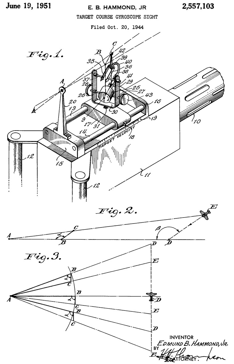
2557103 Target course gyroscope sight, Jr Edmund B Hammond, Sperry Corp, Filed: 1944-10-20, Pub: 1951-06-19
appears to be for use on a flexible mounted machine gun, like in a flying fortress.
2588414 Aspherical corrector lens for optical systems, Rosin Seymour, Farrand Optical Co Inc, 1952-03-11
2609729 Bombing instrument for aircraft, Wilkenson Erik Alvar, Faxen Per Torsten, 1952-09-09 - improved dive bombing - auto release of bomb - improved dive bombing
2719457 Scanning telescope having astigmatized pupil, Robert W Tripp, Farrand Optical Co Inc, 1955-10-04 - a hemisphere sight which will operate in a polar coordinate system the same as that employed in fire control systems
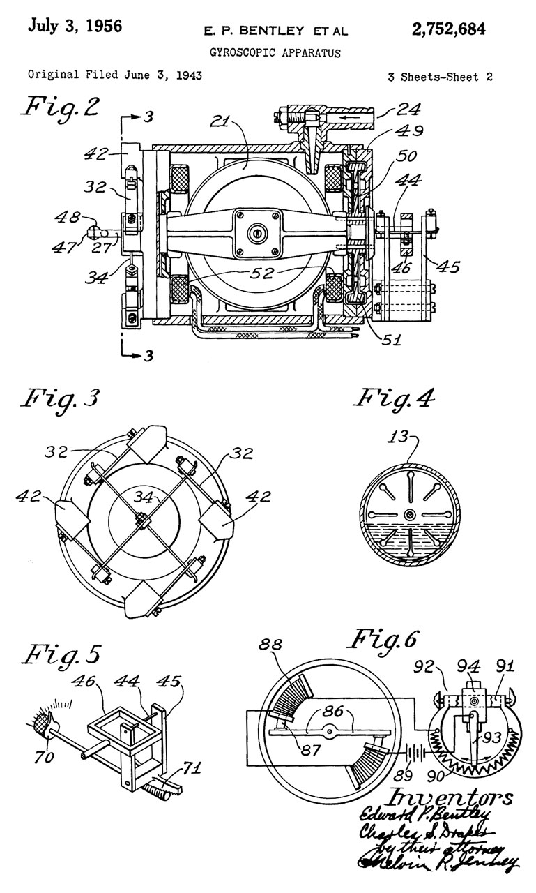
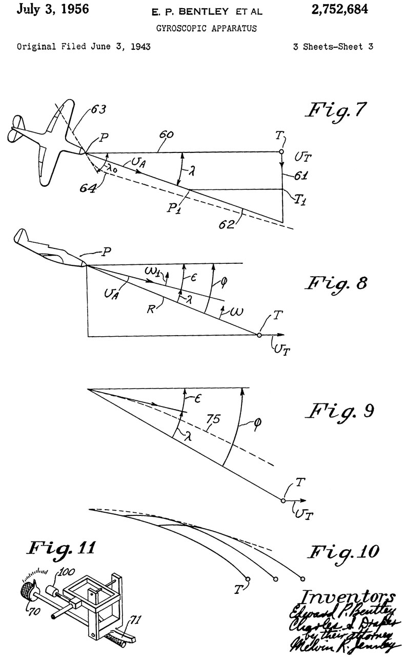
2752684 Gyroscopic apparatus, Edward P Bentley, Charles S Draper (Wiki), Research Corp, 1956-07-03 - lead computing sight for airplane, uses 2 gyros - useful for attacking stationary target if there is wind
2949808 Aerial gunsight, James E Thurow, Motors Liquidation Co, 1960-08-23 - "The invention has for its principal object to provide a lead predicting type sight head of the above character which is a true spherical, coordinate, angular repeater and yields a spherical, coordinate angle presentation that is free of optical droop errors and does not need any electronic or mechanical compensation." - includes input from RADAR.
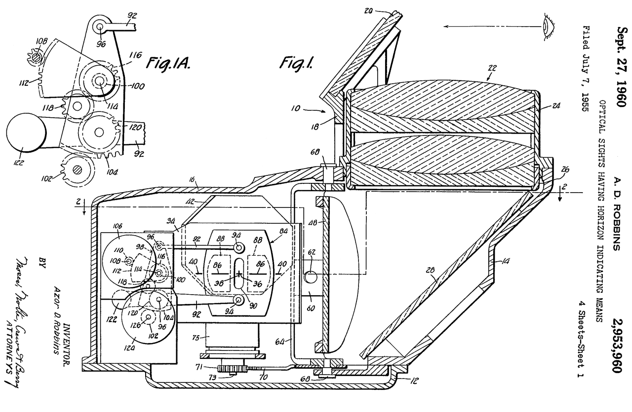
2953960 Optical sights having horizon indicating means, Azor D Robbins, W L Maxson, 1960-09-27, - "It is a primary object of the present invention automatically to include in the sight, either separately or in combination with the fixed image at least, a reticle image representative of the horizon and constantly in coincidence therewith, the purpose being to aid the pilot in the management of the aircraft under conditions when the true horizon is not visible through the combining glass."
I stumbled on this when looking for a W L Maxson patent for the Nuclear bomb sight:
Computer Unit, Computer Group, Bombing, Type K-4
3145248 Optical sight displacing glass, James A Shuping, 1964-08-18 -"... a displacing glass attachment for reflex type optical gun sights to provide such sights with a low altitude bombing capability. "


Related
40mm Grenades, rifle grenades, Bazooka, rockets
A-10A Aircraft Sextant -
Abrams Universal Sun Compass SC-1 -
AC_D500 Astro-Compass MkII - transit with no optics
Aircraft -
Aircraft Pilot's Standby Magnetic Compass B-16
Altimeters & Barometers
AN-M8 Pyrotechnic Flare Pistol - used in aircraft
ARM-511 TACAN/DME Ramp Test Set
ARN89 AN/ARN-89 Direction Finder Set
Astro Astronomy
Aviation Headsets
Bino_I Table of Binoculars with calculated data as well as my Holding Power Index
BinoPerf Plot of Performance for selected giant binoculars
China Lake (& related) Patents: Sidewinder, VT Fuse, Rockets
CRT-1B Sonobuoy - first model
CRT-3 BC-778 Gibson Girl Survival Beacon Transmitter SCR-578 - used in surval boats
Edgerton - Index to MIT lab notebooks
EdscorpFRF Edscorp Field Range Finder by Edmund Scientific Corp.
EOG Electro-optical Gadgets
FNFAL FN FAL Rifle (.308 Match) - includes various types of sights and ballistics
Gas Masks -
GR Strobotac, Sonar & Krytron
GVS-5 Laser Infrared Observation Device MX-9838/GVS-5
HMMWV HMMWV Hummer 1 ¼-Ton, 4X4
IR_Beacon IR Beacons
IR Gun Sight
M1009 M1009 CUCV TRUCK, UTILITY, TACTICAL, 3/4 TON, 4x4, M1009, Chevrolet K5 Blazer with a diesel engine and 24 electrical system
M12 Panoramic Telescope
M151 M151 MUTT Jeep
M18 M18 IR Binocular
M227 M-227 Signal Lamp Equipment SE-11 - Gun shaped flashlight, trigger, relay, IR Filter option
M79 40 mm Gernade Launcher
MC1 MC-1 Magnetic Compass Calibration Set similar to AN/ASM-344
MCGP Military Collectors Group Posts 1997 - 2000
MD1 Automatic Astro Compass Type MD-1
MILES Multiple Integrated Laser Engagement System (MILES)
MkVHeliograph Mance Type Mk V Heliograph
Nav Navigation Orientation & Position
Navy Mk. 18 Gyro Gun Sight
Optical Bench
Optical Patents
Optical Spectrum Analyzers
Optics Optics, Day & Night
Orion GoScope 80 Table Top Telescope
PAS6 PAS-6 Metascope IR Viewer & IR Source
Pibal theodolite, also see Radiosonde
PRC-96 Navy Lifeboat Survival Radio
Probeye Hughes Probeye Infraed Thermal Viewer
PSO-1Scope Dragunov PSO-1M2 Scope night illumination
S5807 MIL-S-5807A Sextant, Aircraft, Periscopic Kollsman Instrument Corporation MS part no. MS 28011-1
SDU30 SDU-30 Light Marker Distress
SDU5E SDU-5/E Marker Distress Light
Semi-auto Weapons - Sterling Mk 4 (L2A3), , Tavor SAR, Styer AUG, SIG stgw57
Sonobuoy Sonobuoy Based Outdoor Intrusion Detectors & sub hunting sonobuoys - SSQ-57 LOFAR Sonobuoy - T-347/SRT Buoy, Radio Transmitting SOS
Submarines
Survival Electronic Survival Equipment
SurvivalKit post Korean War Survival Kit
T3C Russian T3C Night Vision Image Intensifier
Teledyne Avionics TA-3D Acoustic Ear Impedance Meter - audio testing at altitude for aircraft sound
TMQ34 TMQ-34 Meteorological Measuring Set
Torpedoes - Naval Mines, Hedgehogs, Depth Charges
TS23 TS-23 Light Output & Battery Tester for SDU-5/E Strobe Light
TS24B TS-24B survival Ratio Test Set
RT-159A/URC-4 Survival Radio Receiver-Transmitter
URC68 URC-68 Survival Radio
US Navy Infrared IR Signaling Telescope US/C-3
Weather Weather
References
Ref 1. TM 1-495 Harmonization of Aircraft Fixed Guns and Sights, War Dept., 11 August 1944 - about bore sighting (Wiki)
Flight and Gun Setting for Side Firing Aircraft, July 1977, DTIC_AD0488321, Elgin AFB - AC-47 MINI-gun system.
Ref 2. RAF Fixed Gun-Sight Installation in Hunter Aircraft, Dec 1954, DTIC_AD0101973 - Fixed mounting of the RAF Mk 5 Gyro Gun Sight instead of the prior two position mount to save weight and eliminate the problems caused by slop in the mechanism.
Ref 3. Quorta: Why, in WWII, did the US tend to use four or more .50 caliber machine guns as their offensive fighter aircraft weapon whereas the Axis powers many times used a small cannon such as a 20 mm or there about? - Also for slow W.W.II era planes .50 was safe, but in the age of jets that could fly faster than .50 bullets where shooting yourself was a real problem, the 20mm round was faster/better.
Ref 4. How Soviet Pilots Cheated on Gunnery Tests, 21:29 - It's extremely hard to shoot a jet from a jet so ways were found to cheat on the gunnery tests.
Ref 5. Why Dive Bomber Pilots Started Pulling Out 'Too Late' — And Achieved Perfect Accuracy, 30:04 - high G blackouts.
Links
The Birth of Spooky -
YouTube:The AC-130 is a GUNSHIP on Steroids, 10:00 -
PRC68, Alphanumeric Index of Web pages, Contact, Products for Sale
Page Created 2018 Sep 18